Digital conversion device and power conversion device
A power conversion device, digital conversion technology, applied in the direction of output power conversion device, analog-to-digital converter, analog-to-digital conversion, etc.
- Summary
- Abstract
- Description
- Claims
- Application Information
AI Technical Summary
Problems solved by technology
Method used
Image
Examples
Embodiment approach 1
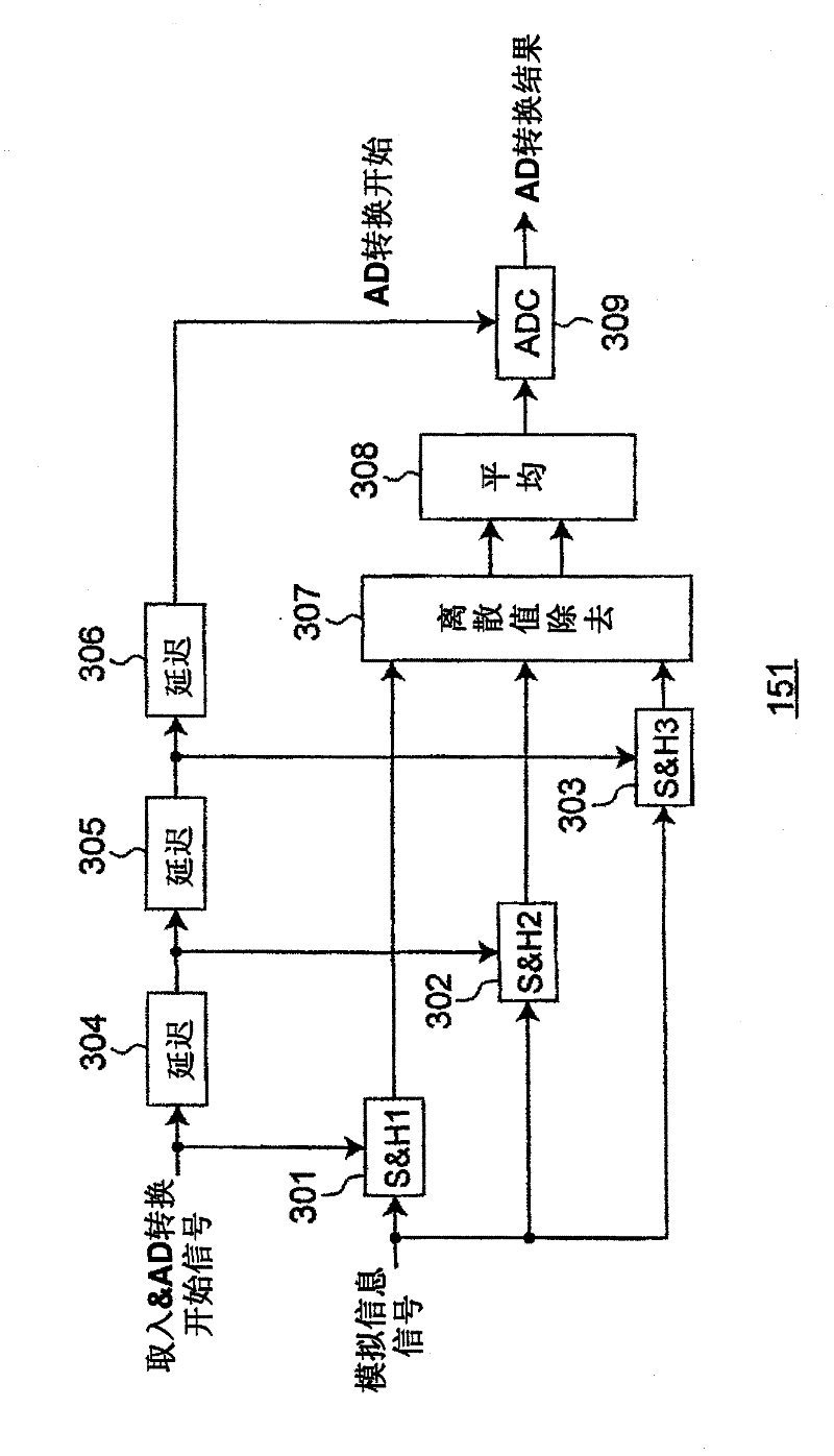
[0040] The power conversion device according to Embodiment 1 of the present invention includes an AD converter that samples and holds current values at intervals shorter than the time required for conversion to digital information. The digitally converted output with noise removed internally realizes stable and high-precision control. The power conversion device of the present embodiment is built in, for example, a system such as an air conditioner.
[0041] 1.1 Structure of power conversion device
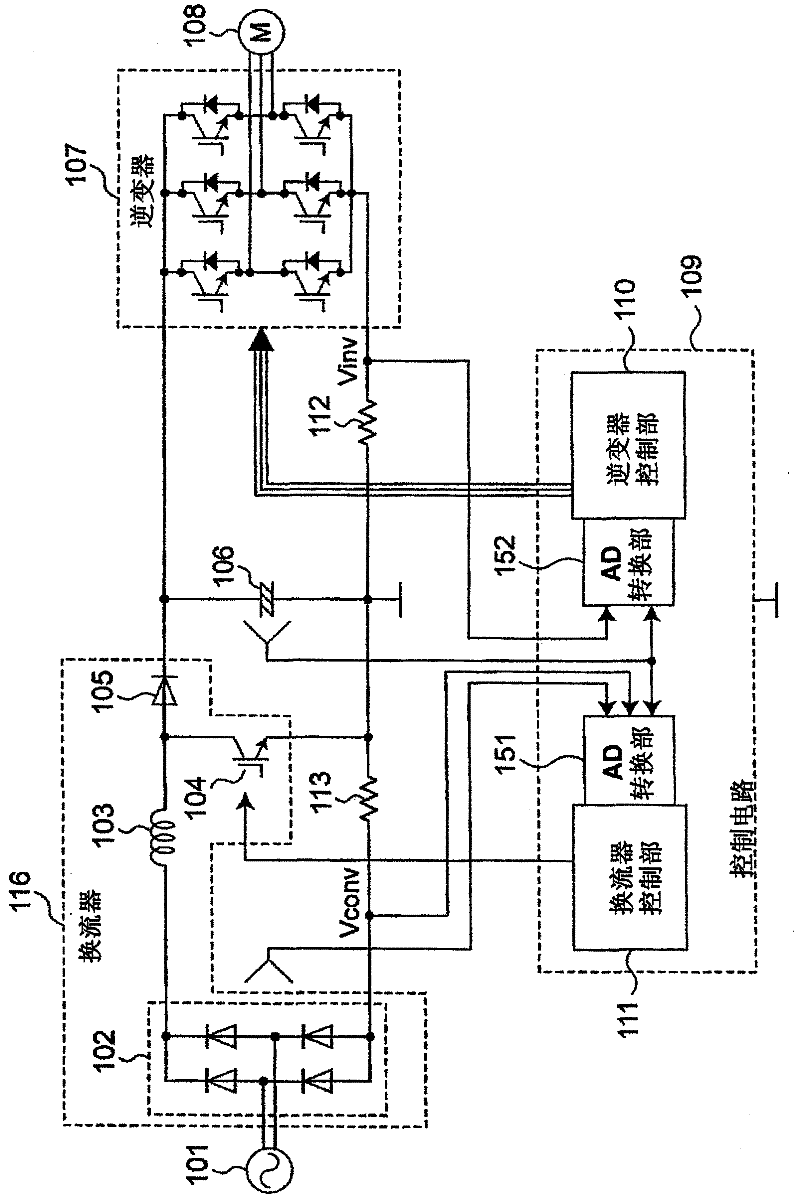
[0042] figure 1 An overall configuration diagram showing the power conversion device according to Embodiment 1 of the present invention. The power conversion device of this embodiment includes: an active inverter circuit (DC power conversion unit) 116 that converts the AC power output from the AC power supply 101 into DC power; The smoothing capacitor 106 that smoothes the current of the smoothing capacitor 106; the inverter circuit (AC power conversion unit) 107 that convert...
Embodiment approach 2
[0070] The power conversion device of Embodiment 2 differs from the power conversion device of Embodiment 1 in the configuration and operation of AD conversion units 151 and 152 . The AD converters 151 and 152 of Embodiment 1 perform AD conversion at the end. On the other hand, in Embodiment 2, AD conversion is performed after sample hold. That is, an AD conversion circuit is provided next to each sample-and-hold circuit, and after all the information is temporarily converted into digital information, discrete value removal and averaging are performed by digital operations. Accordingly, the AD conversion units 151 and 152 can be realized more easily as a large scale integrated circuit (LSI). Embodiment 2 is the same as Embodiment 1 except for the configuration and operation of AD converters 151 and 152 .
[0071] Image 6 The configuration of the AD converter 151 according to Embodiment 2 of the present invention is shown. AD conversion section 152 also has Image 6 struc...
Embodiment approach 3
[0077] The power conversion device of Embodiment 3 differs from the power conversion devices of Embodiments 1 and 2 in the configuration and operation of AD converters 151 and 152 . In the AD converters 151 and 152 of Embodiment 1 and Embodiment 2, the discrete value removal circuit 307 removes the farthest values, but in Embodiment 3 the maximum and minimum values are removed. In Embodiment 3, the configuration and operation other than the above are the same as those in Embodiment 1.
[0078] Figure 8 The structure of the AD converter 151 of this embodiment is shown. In addition, the AD conversion unit 152 also has Figure 8 structure shown. Hereinafter, the configuration and operation of the AD conversion unit 151 will be described as an example. The AD converter 151 of this embodiment does not use figure 2 The discrete value removing circuit 307 is shown, but the maximum and minimum value removing circuit 407 is used which removes the signal having the maximum valu...
PUM
 Abstract
Description
Claims
Application Information
 - R&D
- Intellectual Property
- Life Sciences
- Materials
- Tech Scout
- Unparalleled Data Quality
- Higher Quality Content
- 60% Fewer Hallucinations
Browse by: Latest US Patents, China's latest patents, Technical Efficacy Thesaurus, Application Domain, Technology Topic, Popular Technical Reports.
© 2025 PatSnap. All rights reserved.Legal|Privacy policy|Modern Slavery Act Transparency Statement|Sitemap|About US| Contact US: help@patsnap.com


