
Cold extrusion die for double end pipe joint

A cold extrusion, double-ended tube technology, applied in metal extrusion dies and other directions, can solve problems such as time-consuming and labor-intensive, inability to complete product demoulding, and failure to meet precision requirements.

Active Publication Date: 2011-10-05
南通市通州区俊朗建筑工程有限公司
View PDF6 Cites 7 Cited by
  • Summary
  • Abstract
  • Description
  • Claims
  • Application Information

AI Technical Summary

Problems solved by technology

[0003] 1) The surface of the product produced by the casting mold is rough, and there are defects such as blisters, pores, burrs, cracks, etc., which cannot meet the precision requirements and affect the quality of the product;
[0004]2) When using a machine tool to finish the double-head pipe joint blank after casting, due to the need to cut off the excess metal material and rough surface of the double-head pipe joint blank, The amount of cutting is large, resulting in waste of materials and increasing the production cost of manufacturing double-ended pipe joints
[0006]The disadvantage of this cold extrusion die is: when demoulding, the upper and middle mold sets must be removed in order to make the extruded product protrude from the bottom. Take it out from the mold; for the next extrusion, put the semi-finished product to be processed into the lower punch, and then install the middle mold sleeve and the upper mold sleeve in sequence, and then perform the next extrusion
During the production process of this mold, the upper and middle mold sleeves are installed and removed many times, which is time-consuming and labor-intensive, which increases the labor cost, and even the demoulding of the product cannot be completed.

Method used


Image

  • Cold extrusion die for double end pipe joint
  • Cold extrusion die for double end pipe joint
  • Cold extrusion die for double end pipe joint

Examples


Embodiment Construction

[0021] Below in conjunction with accompanying drawing and specific embodiment the present invention is described in further detail:

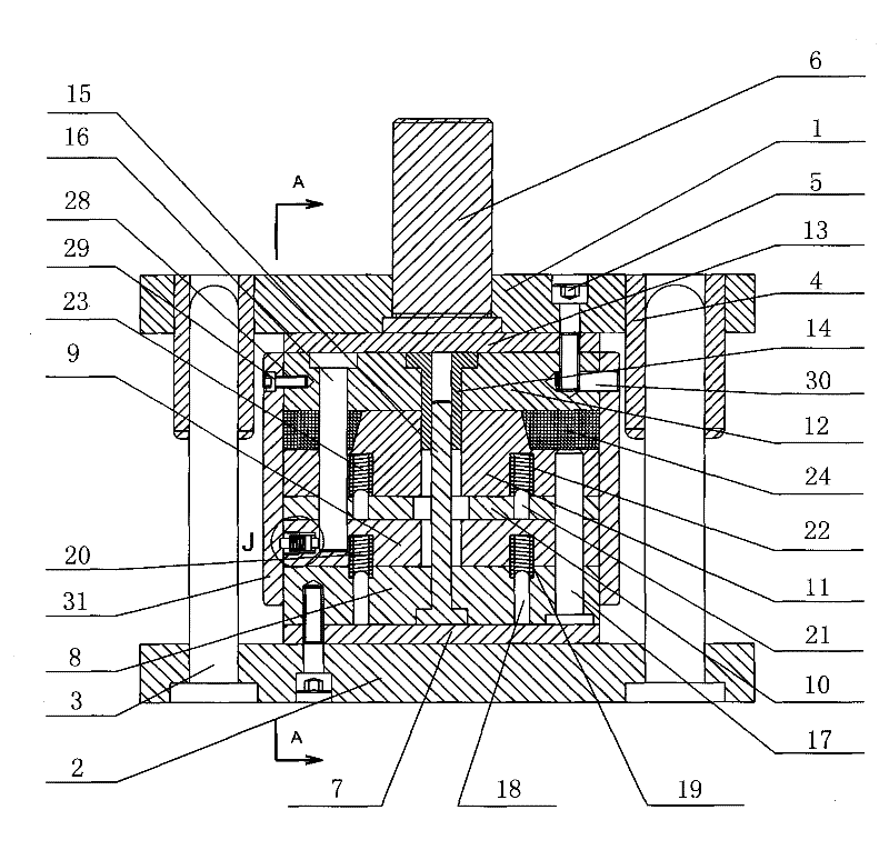
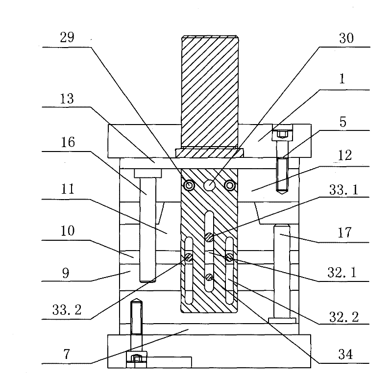
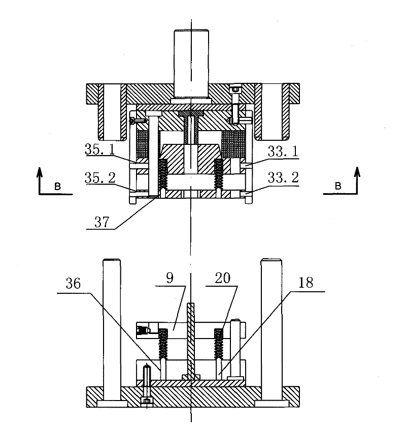
[0022]The cold extrusion die for the twelve-corner double-head pipe joint includes an upper template 1, a lower template 2, two guide posts 3, two guide sleeves 4, four hexagon socket bolts 5, and a die handle 6. The mold frame, the mold handle 6 is embedded in the center position of the upper template 1, and the lower end of the mold handle 6 is supported on the upper mold backing plate 13. It also includes the upper end of the following template 2 as the base surface, and there are a lower mold backing plate 7, a lower mold fixing plate 8, a lower mold sleeve 9, a middle mold sleeve 10, and an upper mold sleeve 11 from bottom to top. , a patrix fixed plate 12, a patrix backing plate 13; Wherein the upper formwork 1, the patrix backing plate 13, the patrix fixed plate 12 are fastened and connected with bolts 5 to form a whole; wherein the lower...


PUM


Abstract

The invention discloses a cold extrusion die for a double end pipe joint. The cold extrusion die comprises an upper die fixing plate, a lower die fixing plate, an upper die sleeve, a middle die sleeve, a lower die sleeve and upper die guide pillars, wherein an inner bore of the middle die sleeve is in a twelve angle plum flower shape, and ejection devices are arranged between the lower die fixingplate and the lower die sleeve, and between the middle die sleeve and the upper die sleeve. The cold extrusion die also comprises support plates fixed on a left side and a right side of the upper diefixing plate, wherein the support plates are also located on a left side and a right side of the upper die sleeve, the middle die sleeve, the lower die sleeve and the lower die fixing plate, and are flexibly connected with the upper die sleeve and the middle die sleeve. The cold extrusion die for double end pipe joint of the present invention can be applied to manufacture of double end pipe jointin a twelve angle plum flower shape, and has advantages of decreased production costs and easy demoulding.

Description

technical field [0001] The invention relates to a cold extrusion die, in particular to a cold extrusion die for a double-ended pipe joint. Background technique [0002] At present, in the manufacture of double-ended pipe joint products with outer wires, the double-ended pipe joint is generally used to form a casting mold to form a blank first, and then the cast blank is finished with a machine tool, and finally the finished work is finished with a die sleeve or a lathe. The double-headed pipe joints are processed with external threads. Adopt above technology to have following defective: [0003] 1) The surface of the product produced by the casting mold is rough, and there are defects such as blisters, pores, burrs, cracks, etc., which cannot meet the precision requirements and affect the quality of the product; [0004] 2) When using a machine tool to finish the cast double-head pipe joint blank, due to the need to cut off the excess metal material and rough surface of th...

Claims


Application Information

Patent Timeline
IPC IPC(8): B21C25/02B21C35/02B21C37/28
Inventor 陆颂荫
Owner 南通市通州区俊朗建筑工程有限公司
Learn More