
Active sleeve-withdrawing device for hose assembling machine

A technology of assembly machine and sleeve withdrawal, which is applied in metal processing, metal processing equipment, manufacturing tools, etc. It can solve the problems that the ferrule cannot put the hose in, does not meet the expected requirements, and the top of the ferrule is aggressive.

Active Publication Date: 2011-10-05
浙江本发科技有限公司
View PDF5 Cites 9 Cited by
  • Summary
  • Abstract
  • Description
  • Claims
  • Application Information

AI Technical Summary

Problems solved by technology

However, during this period of operation, failures sometimes occur: because the out-of-roundness of individual ferrules or hoses is not up to the standard, the ferrules cannot fit the hoses, or the diameters of the two do not match, and the tension of the fit is not enough. , when taking the sleeve head back, the ferrule did not fit on the top of the hose as expected, but stayed in the sleeve head and followed it out, which buried a hidden danger for the subsequent process: when the sleeve is removed next time, due to There is an old ferrule in the take-off head, and the ejector rod of the take-off device cannot push the new ferrule into the take-off head
In the process of hardtop, the cylinder is often damaged

Method used


Image

  • Active sleeve-withdrawing device for hose assembling machine
  • Active sleeve-withdrawing device for hose assembling machine
  • Active sleeve-withdrawing device for hose assembling machine

Examples


Embodiment Construction

[0029] Further elaborate the present invention below in conjunction with embodiment and accompanying drawing:

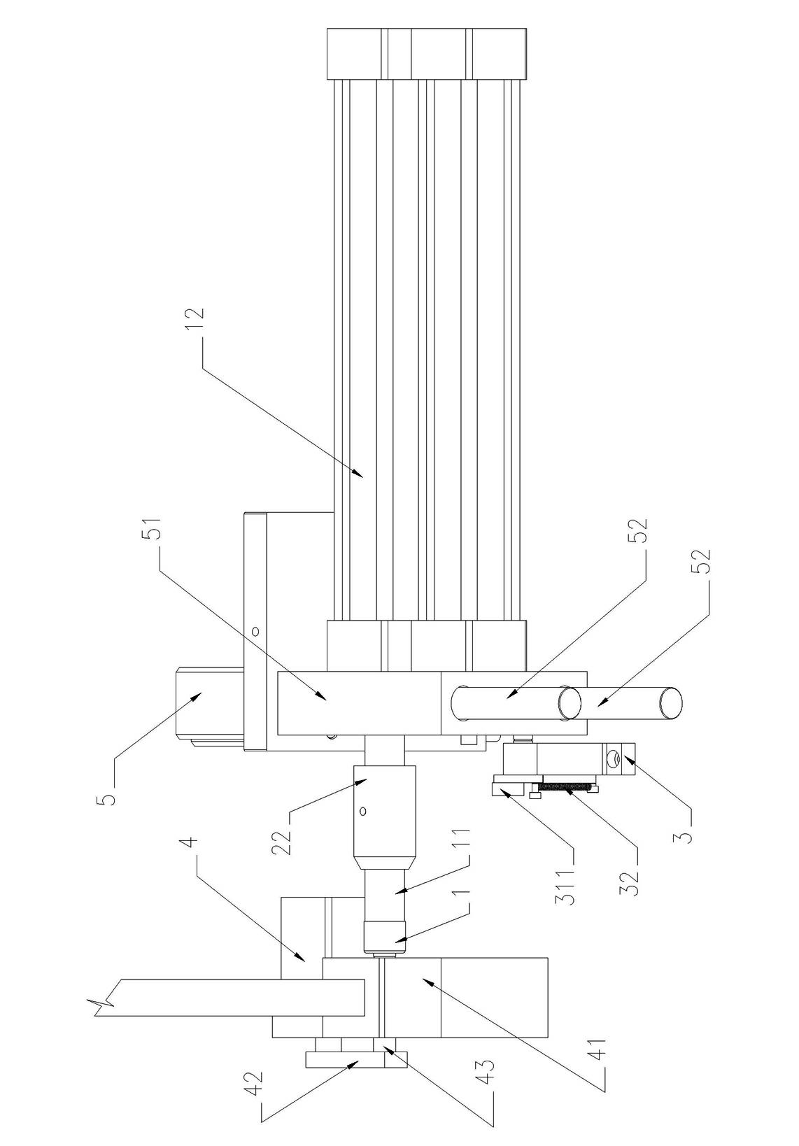
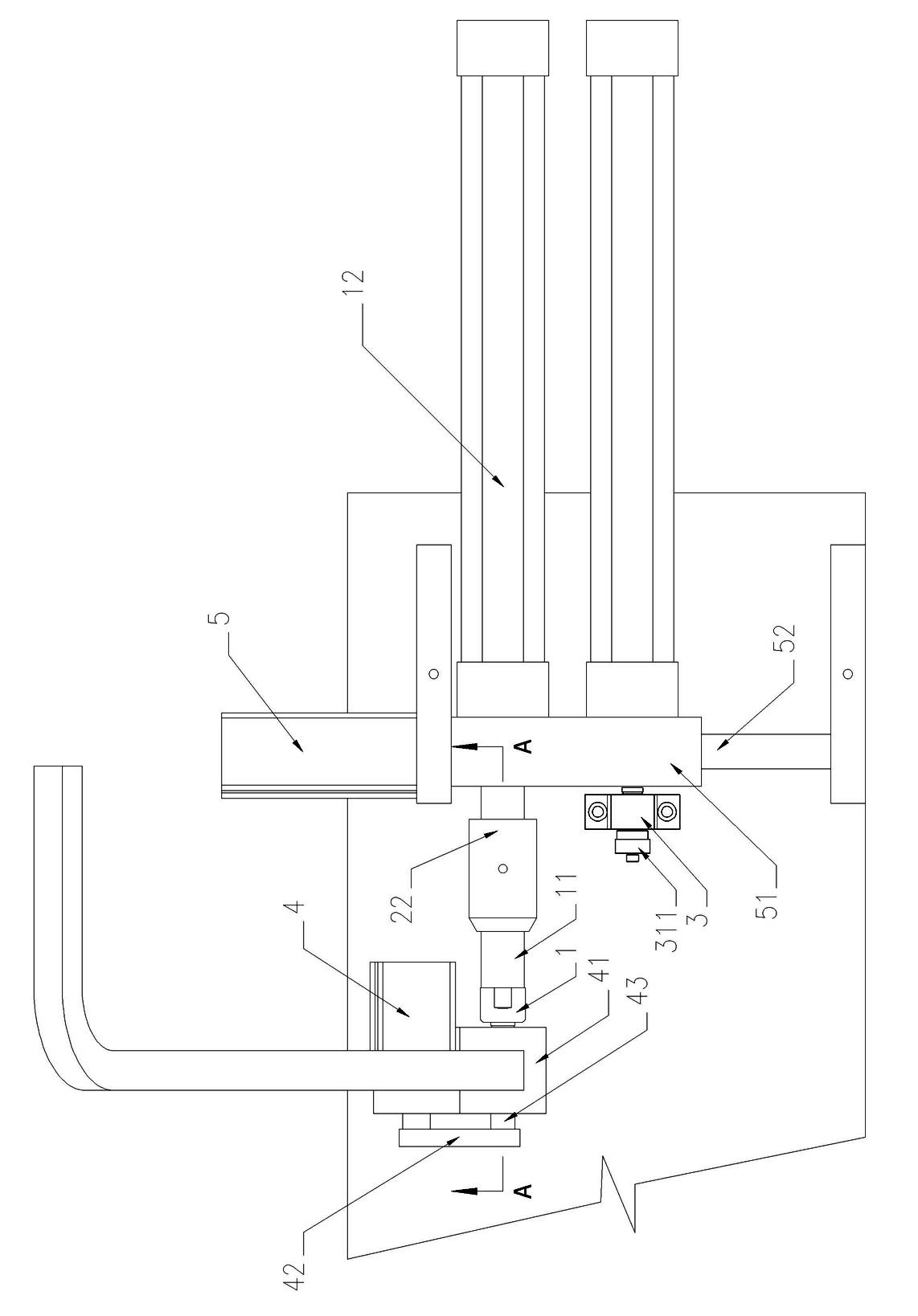
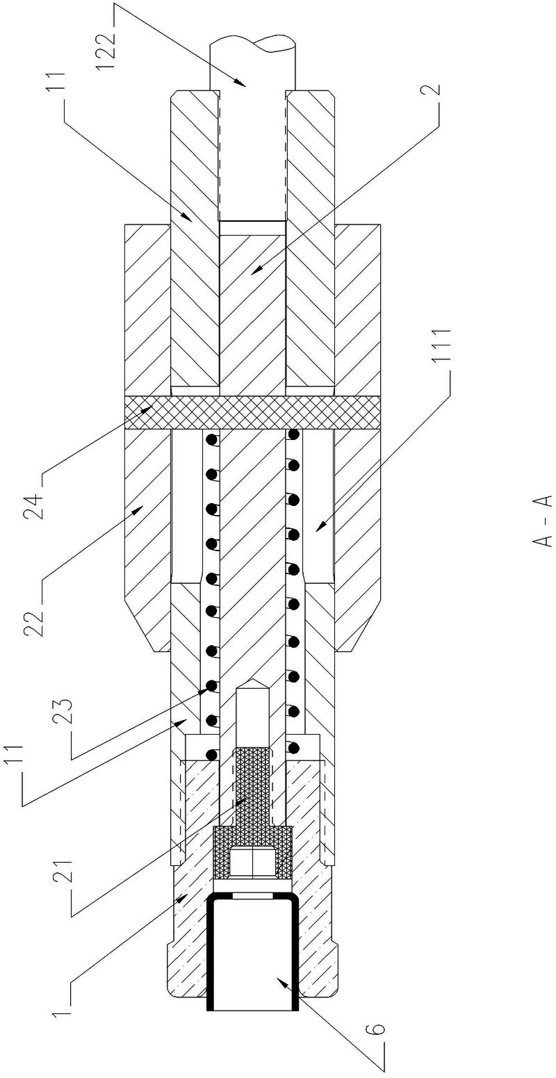
[0030] Such as Figure 1 to Figure 6 The active retracting device of the hose assembly machine shown in the figure is controlled by the microcomputer control system to control the movement direction and movement time of each cylinder, so as to realize the automatic operation of each mechanical part; The sheet 42 and mandrel 43 move to the left, and the ferrule 6 in the cover base 41 falls into the top cover position, as figure 1 figure 2 As shown, at the same time, the lateral movement cylinder 5 pulls the displacement cylinder seat 51, so that the sleeve head 1 is aligned with the sleeve removal position of the sleeve base 41, and the cylinder ejector rod 122 of the cylinder 12 ejects the sleeve head 1 and stops at the sleeve removal position. The "door" is waiting.

[0031] Then the ejector rod of getting cover cylinder 4 under microcomputer control drives conn...


PUM


Abstract

The invention relates to an active sleeve-withdrawing device for a hose assembling machine. The device comprises a sleeve-taking head, a connecting rod, a cylinder, a cylinder jacking rod, a sleeve-withdrawing jacking rod, a hexagon screw, a sleeve-withdrawing bolt, a pressing spring, a sleeve-withdrawing bolt pin, a sleeve-withdrawing positioning base, a cam, a tension spring, a shifting cylinder and a shifting cylinder base. After a sleeve ring is sent out by the cylinder, the cylinder withdraws, and then the sleeve-withdrawing bolt and the connecting rod withdraw together; after withdrawing for a short time, the lower part of a rear end of the sleeve-withdrawing bolt contacts with the cam and the pressing spring is pressed, but the connecting rod and the sleeve-taking head fixed on the connecting rod continue withdrawing under the pulling of the cylinder jacking rod; the sleeve-withdrawing bolt pin slides in a circular waist through hole of the connecting rod; the sleeve-withdrawing jacking rod is fixed and the sleeve-taking head withdraws; and the hexagon screw which is fixed at the top end of the sleeve-withdrawing jacking rod extends from the sleeve-taking head under the action of the relative motion of the sleeve-withdrawing jacking rod and the sleeve-taking head, so that the sleeve ring which is maintained in the sleeve-taking head can be pushed out and the smooth operation of the next circulation is ensured.

Description

technical field [0001] The invention relates to a hose processing machine, in particular to an active sleeve withdrawal device of a hose assembly machine. Background technique [0002] At present, in the production of the hose industry, most of the assembly methods for the hose are based on manual operations. The work content is to fix the three parts of the ferrule, the core and the nut at each top of the hose, and require the nut to be able to rotate but not Can not move. [0003] In the above assembly process, the core must be inserted into the inner wall of the hose. Due to the small fit gap, soapy water is often applied on the outer wall of the core as a lubricant; Sharp, workers often stabbed their fingers with metal wires when assembling collars and were dripping with blood, so they had to be replaced. If you want to wear stab-resistant gloves to work, the product quality cannot be guaranteed due to clumsy movements and low efficiency, and the production cost remain...

Claims


Application Information

Patent Timeline
IPC IPC(8): B23P19/027
Inventor 梁贤军万春明薛林晓
Owner 浙江本发科技有限公司
Learn More