
Manufacturing process of long-life nitrogen generator

A nitrogen generator and manufacturing process technology, applied in nitrogen compounds, nitrogen purification/separation, chemical instruments and methods, etc., can solve the problems of reduced core performance, short service life, cracks, etc., to improve working life and performance. , the effect of improving the separation efficiency

Inactive Publication Date: 2020-05-19
SHENZHEN ZHONGLIAN AEROSPACE TECH CO LTD
View PDF6 Cites 0 Cited by
  • Summary
  • Abstract
  • Description
  • Claims
  • Application Information

AI Technical Summary

Problems solved by technology

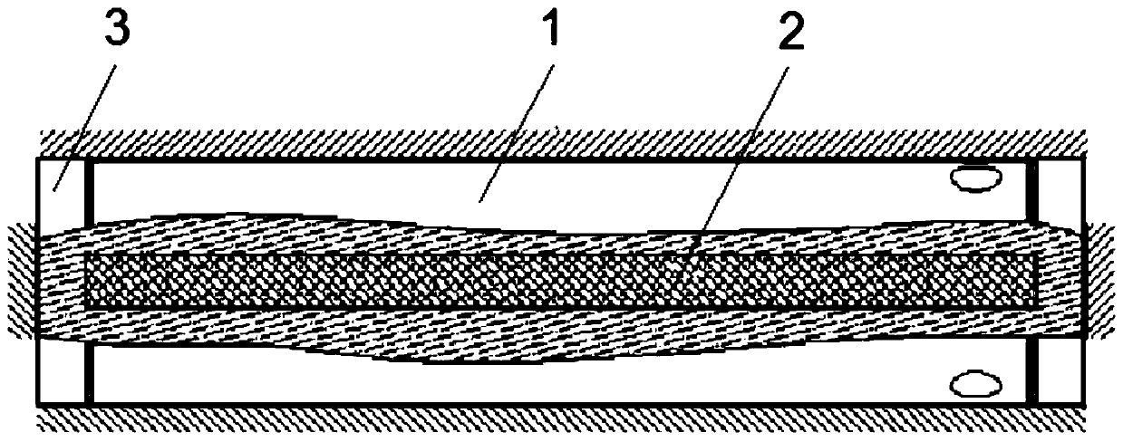
Existing nitrogen generators are mainly composed of cores made of fiber bundles 1, support rods 2, heads 3 and shells, etc., such as figure 1 The nitrogen generator used on the shown aircraft mainly supports the core body through a support rod 2 made of polyimide inside the core body. The area of ​​the end surface of the head 3 is larger than the area of ​​the end surface of the support rod 2, so when the core is ventilated, the contact position between the support rod 2 and the head 3 is easily damaged and cracks occur, such as figure 1 As shown, if there is a crack in the core inlet head 3, the crack can be repaired at this time, but if there is a crack in the core outlet head 3, it can only be scrapped. The service life of the nitrogen generator produced by this structure is only About 7500H, the service life is short
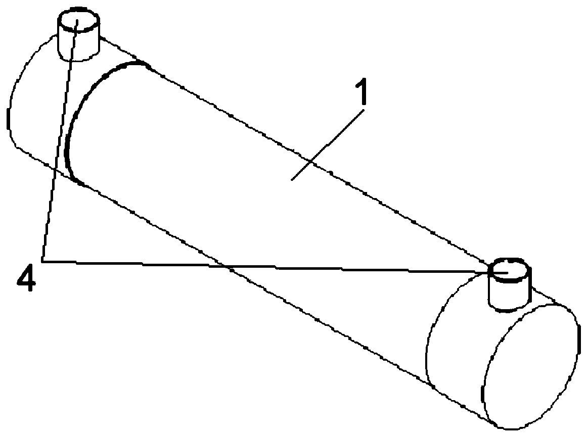
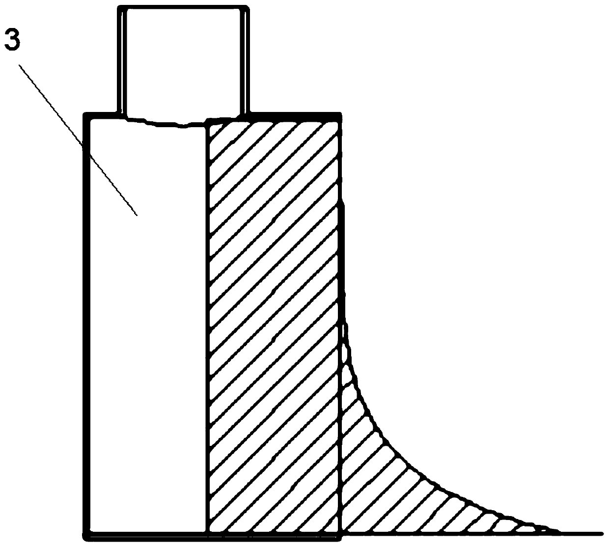
[0003] At present, the head on the core body of the foreign original factory is generally made by centrifugal glue filling, such as figure 2 As shown, during manufacture, the fiber bundle 1 is bundled into a cylinder to form a core and placed horizontally, and then the middle of the core is used as the axis to make a circular motion, and epoxy resin glue is poured into the glue inlet 4 to start the centrifugation Machine, so that the epoxy resin glue maintains centrifugal motion, and then wait for the epoxy resin glue to solidify, such as image 3 As shown, after the epoxy resin is solidified, the core body is taken out. At this time, the head formed by the epoxy resin glue solidified at both ends of the core body will have an arc-shaped concave edge. At this time, the core body can separate oxygen fibers. Reduced fiber filaments in the bundle, reducing the performance of the core when used in a nitrogen generator

Method used


Image

  • Manufacturing process of long-life nitrogen generator
  • Manufacturing process of long-life nitrogen generator
  • Manufacturing process of long-life nitrogen generator

Examples


Embodiment Construction

[0030] The technical solutions of the present invention will be clearly and completely described below in conjunction with the accompanying drawings. Apparently, the described embodiments are some of the embodiments of the present invention, but not all of them.

[0031] The components of the embodiments of the invention generally described and shown in the figures herein may be arranged and designed in a variety of different configurations. Accordingly, the following detailed description of the embodiments of the invention provided in the accompanying drawings is not intended to limit the scope of the claimed invention, but merely represents selected embodiments of the invention.

[0032] Based on the embodiments of the present invention, all other embodiments obtained by persons of ordinary skill in the art without making creative efforts belong to the protection scope of the present invention.

[0033] In the description of the present invention, it should be noted that the...


PUM


Abstract

The invention discloses a manufacturing process of a long-life nitrogen generator. The manufacturing process comprises the following steps: taking materials, processing end sockets, cutting, winding of film, tapping, mounting a shell, pouring glue, and mounting a sealing cover and a tail cover to obtain the long-life nitrogen generator. The manufacturing process has the advantages of improving theseparation efficiency, prolonging the service life and the like.

Description

technical field [0001] The invention belongs to the technical field of nitrogen generator manufacturing, and in particular relates to a manufacturing process of a high-life nitrogen generator. Background technique [0002] The nitrogen generator is a device that uses a bundle composed of multiple hollow fiber membranes to separate oxygen and nitrogen in the air. The side wall of the hollow fiber bundle can pass through oxygen molecules, but nitrogen molecules cannot pass through, so it can separate oxygen and nitrogen in the air. Nitrogen separation. Existing nitrogen generators are mainly composed of cores made of fiber bundles 1, support rods 2, heads 3 and shells, etc., such as figure 1 The nitrogen generator used on the shown aircraft mainly supports the core body through a support rod 2 made of polyimide inside the core body. The area of ​​the end surface of the head 3 is larger than the area of ​​the end surface of the support rod 2, so when the core is ventilated, t...

Claims


Application Information

Patent Timeline
Patent Type & Authority Applications(China)
IPC IPC(8): C01B21/04B01D53/22B01D63/02
CPCB01D53/228B01D63/022C01B21/0444C01B2210/0012C01B2210/0045
Inventor 薛进李祥
Owner SHENZHEN ZHONGLIAN AEROSPACE TECH CO LTD
Learn More