Supercharge Your Innovation With Domain-Expert AI Agents!

Sectioned lead screw type lifting device

A technology of lifting device and lead screw, which is applied in the direction of transmission device, belt/chain/gear, mechanical equipment, etc., can solve the problems of insufficient safety of jacking structure, large horizontal component force, geometric deformation, etc., and is suitable for large batches The effect of manufacturing, good safety, and small footprint

Inactive Publication Date: 2013-04-03
刘仙昌
View PDF5 Cites 0 Cited by
  • Summary
  • Abstract
  • Description
  • Claims
  • Application Information

AI Technical Summary

Problems solved by technology

The above two published patents are rigid chains hinged by flexible chains and multi-segment racks, which effectively reduce the volume of the lifting device itself. The foundation pit is shallow and can be installed and used in a relatively narrow space, and provides However, they all have the following deficiencies: First, as the rigid section of the jacking load-bearing carrier, whether it is a chain structure or a gear structure, the meshing part with the driving part (the former is a sprocket, and the latter is a gear) It is on one side of the rigid section, so the force at both ends of the rigid section is unbalanced, which will generate a large horizontal force component. When the load is too large, the rigid section is prone to broken teeth and bending, which will cause the load of the entire device The ability is limited; second, in the jacking state, once the external drive device, transmission mechanism, etc. fail, the above two devices will fail, so that the lifted device or object will suddenly sink under the action of gravity, which is easy to cause Economic loss, forming a greater safety hazard, especially the lifting platform with personnel activities, such as lifting stage, lifting stand, the safety of these lifting structures is obviously insufficient; third, the driving parts in the aforementioned two devices are in contact with the rigid section The area of ​​the abutting surface of the part is small, and under the long-term load state, it is easy to produce geometric deformation, which will lead to the failure of the device

Method used


Image

  • Sectioned lead screw type lifting device
  • Sectioned lead screw type lifting device
  • Sectioned lead screw type lifting device

Examples


Embodiment

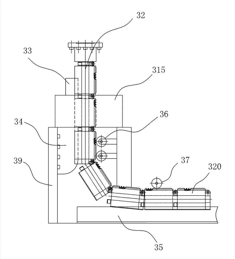
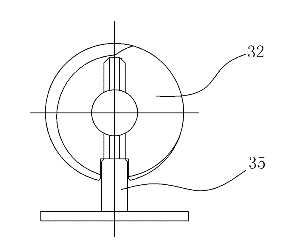
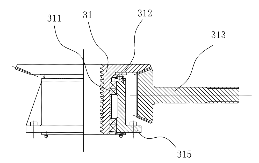
[0031] Embodiment: a segmented screw type lifting device of the present invention, as attached figure 1 , attached image 3 , attached Figure 10 , attached Figure 11 , attached Figure 12 As shown, it includes a lead screw 32 that can be connected to the bottom of the lifting platform 4, and a rotating nut 31 that can be rotated under the actuation of an external drive device. In the structure bent to one side, the vertical section between the rotating nut 31 and the lifting platform 4 is rigid, and the rest is flexible; the two ends of the segmented screw 320 are parallel to each other. The engaging thread of the segmented lead screw 320 and the rotating nut 31 is a zigzag thread. The larger end of the rotary nut 31 thread angle is set downward.

[0032] as attached Figure 4 , attached Figure 5 , attached Image 6 , attached Figure 7 , attached Figure 8 , attached Figure 9 As shown, the two end surfaces 321 and 322 of the segmented lead screw 320 are planes ...


PUM


Abstract

The invention relates to a sectioned lead screw type lifting device. The device comprises a lead screw which can be connected to the bottom of a lifting table, and a rotating nut which can rotate under the actuation of an external driving device, wherein the lead screw is formed by hinging a plurality of sections of lead screws and has a structure capable of bending towards one side; a vertical section positioned between the rotating nut and the lifting table is rigid and the other sections are flexible; upper and lower end faces of the sectioned lead screw on the vertical section positioned between the rotating nut and the lifting table are pressed against end faces of adjacent sectioned lead screws respectively, so that the vertical section becomes a rigid rod piece which can transmit gravity of the table to the rotating nut; and compared with a transmission structure for transmitting load on a single side, a spiral structure is stressed uniformly and has higher loading capacity. Because a spiral connecting structure has self-locking capacity, when an external driving or transmission mechanism fails, the rotating nut can immediately and automatically lock the lead screw, so thatthe condition that the lifting table is settled is avoided; therefore, the safety is greatly improved.

Description

technical field [0001] The invention relates to a lifting device, in particular to a segmented screw type lifting device. Background technique [0002] In view of the shortcomings of the traditional lifting device itself, which takes up a large space and the lifting stroke is limited, some inventors proposed an improved technology called "flexible lifting device" (patent number: ZL 200320lll378.6), which includes motor deceleration The transmission mechanism between the device and the lifting table is composed of a sprocket and a flexible chain, wherein the flexible chain is rigid in the vertical section and flexible in the curved section in contact with the sprocket. Another inventor proposed another improved structure named "a flexible rack type lifting device" (patent number: ZL 200420020574.7), which includes a fixed bracket fixed to the ground, a drive box, a lifting bracket, and a For the lifting device of the lifting bracket, the lifting device passes through the fix...

Claims


Application Information

Patent Timeline
Patent Type & Authority Patents(China)
IPC IPC(8): F16H25/20
Inventor 刘仙昌王文明肖东林
Owner 刘仙昌
Features
  • R&D
  • Intellectual Property
  • Life Sciences
  • Materials
  • Tech Scout
  • Unparalleled Data Quality
  • Higher Quality Content
  • 60% Fewer Hallucinations
Learn More