Simulative calculation method for engine lubrication system

A lubrication system and simulation calculation technology, applied in the field of simulation calculation of the lubrication system, can solve the problems of waste of manpower and material resources, inability to effectively control the performance of the lubrication system, and inability to control the performance of the lubrication system, and achieve the effect of optimal design

Active Publication Date: 2011-10-05
CHERY AUTOMOBILE CO LTD
View PDF1 Cites 10 Cited by
  • Summary
  • Abstract
  • Description
  • Claims
  • Application Information

AI Technical Summary

Problems solved by technology

However, there is a certain blindness in the design of the current engine lubrication system. The diameter of the oil passage, the bearing clearance, and the size of the oil pump can only be based on simple empirical formulas or completely refer to the prototype, which often makes it impossible to effectively control the performance of the lubrication system in the initial design stage. Later test costs increase
Waste a lot of manpower an

Method used


Image

  • Simulative calculation method for engine lubrication system
  • Simulative calculation method for engine lubrication system
  • Simulative calculation method for engine lubrication system

Examples


Embodiment Construction

[0027] The present invention will be described in detail below according to the accompanying drawings, which is a preferred embodiment of various embodiments of the present invention.

[0028] In this embodiment, a computer numerical simulation is performed on a certain gasoline engine lubrication system. Through this analysis, the purpose of this analysis is to find out the cause of the low oil pressure based on the detailed pressure and flow distribution results; to compare and analyze the results of nozzle diameters and cylinder head orifice diameters of different timing chains, and then to compare nozzles and throttles. Reasonable recommendations are given for orifice diameter.

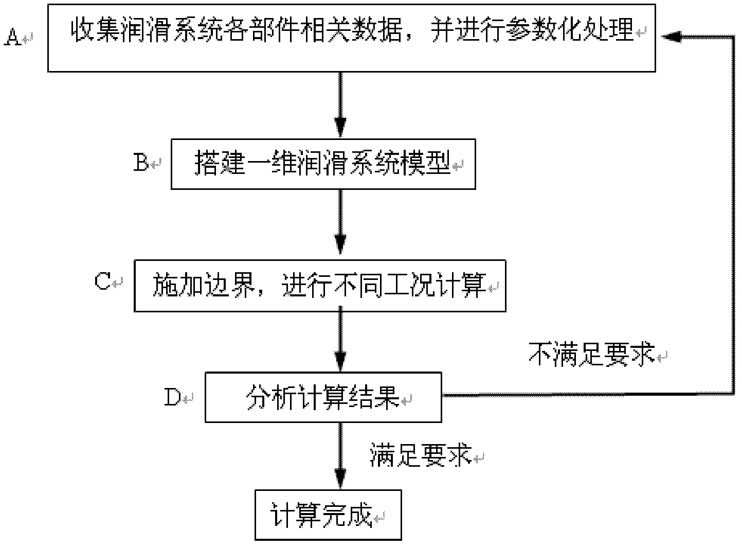
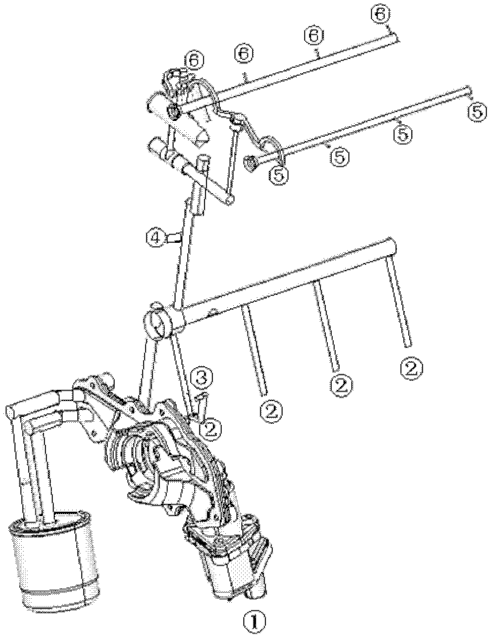
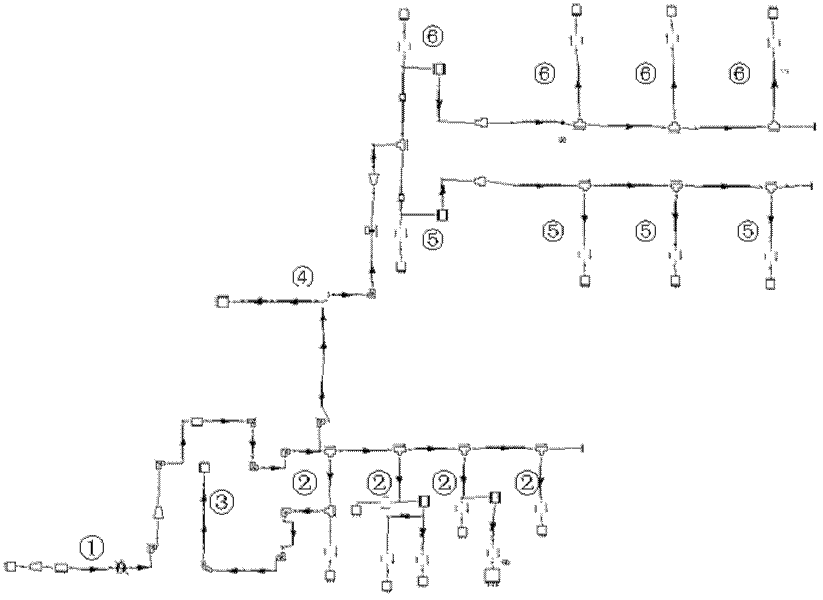
[0029] figure 1 Flow chart for simulation calculation of engine lubrication system. First according to figure 2 The lubrication system model in, collect relevant data, including oil pump characteristic curve; oil pipe length and diameter; main bearing, connecting rod bearing clearance, size, etc. Th...


PUM


Abstract

The invention relates to a simulative calculation method for an engine lubrication system. The method can better guide the design and the development of the lubrication system to improve the development efficiency and save the experimentation cost. Flow analysis is performed on the lubrication system by using a one-dimensional fluid simulation technology in the design method. The method comprisesthe following steps of: A, acquiring related data of each part of the lubrication system, and performing parametric processing; B, building a one-dimensional model; C, performing simulative calculation of different working conditions; and D, analyzing the calculation result, performing optimal design on the lubrication system when the design result does not reach the expectation, and repeating the steps till the calculation result reaches the design index. The simulative calculation method has unique advantages of low cost, high speed, complete data, capability of simulating various differentworking conditions and the like; by using strong functions of a computer and performing one-dimensional simulation on the lubrication system through commercial fluid software, pressure distribution, flow distribution, temperature distribution and the like of the lubrication system can be simulated at the initial stage of design; and by parameter optimization, optimal matching of parameters is obtained. The information acquired by simulation is more comprehensive compared with experimentation, and the simulation can be mutually verified and mutually supplemented with the experimentation. The development efficiency is improved, and massive experimentation cost is saved.

Description

Technical field [0001] The invention belongs to the technical field of automotive engine lubrication systems, and particularly relates to a simulation calculation method of a lubrication system. Background technique [0002] The lubrication system is equivalent to the blood of the engine. The design of the lubrication system must ensure that the blood of the engine is unblocked, and that the pressure and flow are distributed just right. However, the current engine lubrication system design has a certain degree of blindness. The oil passage diameter, bearing clearance, oil pump size, etc. can only be based on simple empirical formulas or completely refer to the prototype, which often makes it impossible to effectively control the performance of the lubrication system at the initial stage of the design. In the future, the cost of testing will increase. Waste a lot of manpower and material resources. [0003] The current engine lubrication system design still has a certain degree of...

Claims


Application Information

Patent Timeline
IPC IPC(8): G06F19/00
Inventor 陶丽芳
Owner CHERY AUTOMOBILE CO LTD
Why Eureka
Try Eureka