
Four-leg robot mechanism based on bionic design

A robot and leg technology, applied in the field of robots, can solve the problems of limited movement flexibility, many connecting rods, redundant degrees of freedom, etc., and achieve the effect of simple and compact overall structure, easy reliability, and convenient installation and disassembly.

Active Publication Date: 2011-10-12
ZHEJIANG UNIV
View PDF10 Cites 71 Cited by
  • Summary
  • Abstract
  • Description
  • Claims
  • Application Information

AI Technical Summary

Problems solved by technology

[0003] Chinese Patent No. CN 101927793 A discloses a "variable structure quadruped robot structure with interchanging crawling and upright motion". The quadruped robot has an organism and four limbs fixed on it. Each limb is controlled by three steering gears. The machine room is a series structure. This structure has many connecting rods and complex structure. It is not suitable for bionic robots that require small and light weight.
At the same time, the body in this structure is a whole, which limits the flexibility of movement
[0004] Chinese patent number CN 101811525 A discloses a "hydraulic-driven quadruped robot moving mechanism with a center of mass adjustment device". The robot mechanism has four legs arranged under the torso, all of which are hydraulically driven, and each leg has redundant degrees of freedom. , increasing the complexity of institutional control
Among them, the universal joint connection component only provides a passive movement form, and cannot be controlled artificially, which is not conducive to the movement and balance control of the mechanism

Method used


Image

  • Four-leg robot mechanism based on bionic design
  • Four-leg robot mechanism based on bionic design
  • Four-leg robot mechanism based on bionic design

Examples


Embodiment Construction

[0015] Further illustrate the present invention below in conjunction with accompanying drawing.

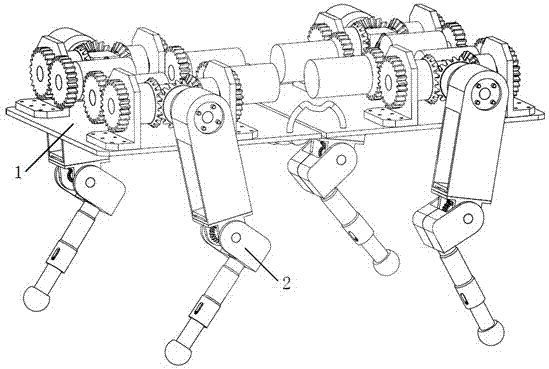
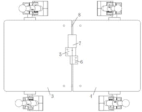
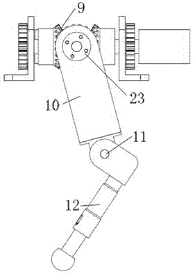
[0016] Such as figure 1 , 2, 3, 4, and 5, the four-legged robot mechanism based on bionic design includes a body frame 1 and four legs 2; the four legs 2 are fixed on the body frame 1; the four legs 2 include a hip 9, a large Leg 10, knee 11 and calf 12; hip 9 connects thigh 10, thigh 10 connects knee 11, knee 11 connects calf 12; body frame 1 includes body front panel 3, body Back plate 4, front rotating flange 5, rear rotating flange 6, first motor 7 and flexible handle 8; Front rotating flange 5 is fixed on the body front plate 3, and rear rotating flange 6 is fixed on the body rear plate 4 , the front rotating flange 5 and the rear rotating flange 6 constitute a rotating pair, the first motor 7 is fixed on the front rotating flange 5, the output shaft of the first motor 7 is connected to the rear rotating flange 6, and the two ends of the flexible handle 8 are respectively B...


PUM


Abstract

The invention relates to a four-leg robot mechanism based on a bionic design. The four-leg robot mechanism consists of a body frame and four legs. The body frame consists of a front plate and a rear plate, two sides of the body frame are provided with flexible handles, and the robot mechanism is convenient to convey; each leg comprises a hip, a huckle, a knee and a crural part; the hip realizes two freedom degrees by adopting a differential bevel gear; the hip and the huckle are connected by an expansion sleeve to realize fast and convenient assembly and disassembly; the bevel gear drive motion is adopted by the knee; the crural part comprises a large cylinder, a small cylinder, a conical spring and a force sensor; and the large cylinder and the small cylinder are connected through the conical spring, so that the external impact force generated in the walking process of the robot can be buffered, the force sensor on a sole can acquire ground acting force, and the external environment can be conveniently sensed in real time and the robot can be subjected to balanced control conveniently. Through the bionic design idea, a spinal cord and a flexible foot mechanism of the robot are stimulated and designed, the flexibility of the robot movement is improved, the impact of the ground to the robot is reduced, and the robot mechanism has a compact structure and is convenient to install.

Description

technical field [0001] The invention belongs to the field of robots and relates to a four-leg robot mechanism based on bionic design. Background technique [0002] With the deepening of human understanding of the natural world, more and more intelligent bionic devices have been developed. Intelligent biomimetic robots take creatures in nature as research objects, use mechanical structures to simulate the movement of biological tissues, and then explore their movement mechanisms. The development of miniaturized, portable and adaptable bionic four-legged robots is of great significance to promote the development of robotics. This kind of bionic robots has broad application and development prospects in scientific research, demonstration teaching and educational entertainment. [0003] Chinese Patent No. CN 101927793 A discloses a "variable structure quadruped robot structure with interchanging crawling and upright motion". The quadruped robot has an organism and four limbs fix...

Claims


Application Information

Patent Timeline
IPC IPC(8): B62D57/032
Inventor 严华朱秋国熊蓉褚健
Owner ZHEJIANG UNIV
Learn More