Conical piece hoisting device

A hoisting device and cone-shaped technology, applied in the direction of transportation and packaging, load hanging components, etc., can solve the problems of low efficiency, easy to bruise workpieces, etc., and achieve the effects of convenient adjustment, less bruises, and simple structure

Inactive Publication Date: 2011-10-12
XIAN AEROSPACEMOTOR MACHINE FACTORY
View PDF6 Cites 12 Cited by
  • Summary
  • Abstract
  • Description
  • Claims
  • Application Information

AI Technical Summary

Problems solved by technology

[0004] In order to solve the disadvantages of low efficiency and easy to bruise workpieces in the prior art, the present invention proposes a hoisting device for conical parts

Method used


Image

  • Conical piece hoisting device
  • Conical piece hoisting device
  • Conical piece hoisting device

Examples


Embodiment 1

[0021] This embodiment is a hoisting device for a cone.

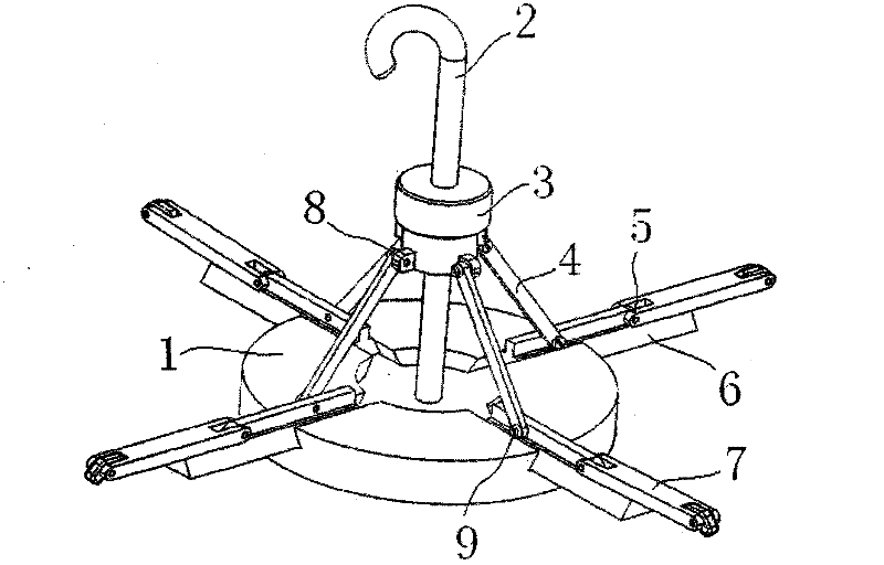
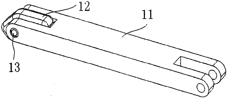
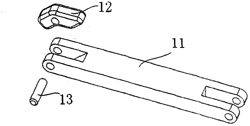
[0022] Such as figure 1 As shown, this embodiment includes a chassis 1 , a boom 2 , an adjustment mechanism 3 , a pull rod 4 , a pin shaft 5 , a slider 6 and a bar body 7 . There is a circular groove in the center of one surface of the chassis 1, and three slider grooves communicating with the groove are evenly distributed around the groove. The slider groove is a trapezoidal groove distributed radially along the chassis 1 . There is a threaded through hole for fixing the suspender 2 in the center of the groove; three sliders 6 having the same cross-section as the slider groove are respectively located in the slider groove, and the two slopes of the slider and the slider groove are clearance fits. A pressing bar body 7 is installed on the upper surface of the slider 6 . The pin hole on the slide block 6 is concentric with the pin hole on the pressure bar 11, the pin hole on the slide block 6 is in clearance fit with ...

Embodiment 2

[0034] This embodiment is a hoisting device for a cone.

[0035] Such as figure 1As shown, this embodiment includes a chassis 1 , a boom 2 , an adjustment mechanism 3 , a pull rod 4 , a pin shaft 5 , a slider 6 and a bar body 7 . There is a circular groove at the center of one surface of the chassis 1, and four slider grooves communicating with the groove are evenly distributed around the groove. The slider groove is an inverted V-shaped groove distributed radially along the chassis 1 . There is a threaded through hole for fixing the suspender 2 in the center of the groove; 4 sliders 6 having the same cross-section as the slider groove are respectively located in the slider groove, and the two slopes of the slider and the slider groove are clearance fits. A pressing bar body 7 is installed on the upper surface of the slider 6 . The pin hole on the slide block 6 is concentric with the pin hole on the pressure bar 11, the pin hole on the slide block 6 is in clearance fit with...

Embodiment 3

[0047] This embodiment is a hoisting device for a cone.

[0048] Such as figure 1 As shown, this embodiment includes a chassis 1 , a boom 2 , an adjustment mechanism 3 , a pull rod 4 , a pin shaft 5 , a slider 6 and a bar body 7 . There is a circular groove in the center of one surface of the chassis 1, and 6 slider grooves communicating with the groove are evenly distributed around the groove. The slider groove is a T-shaped groove distributed radially along the chassis 1 . There is a threaded through hole for fixing the suspension rod 2 in the center of the groove; 6 sliders 6 having the same cross-section as the slider groove are respectively located in the slider groove, and the two slopes of the slider and the slider groove are clearance fits. A pressing bar body 7 is installed on the upper surface of the slider 6 . The pin hole on the slide block 6 is concentric with the pin hole on the pressure bar 11, the pin hole on the slide block 6 is in clearance fit with the pi...


PUM


Abstract

The invention discloses a conical piece hoisting device which is characterized in that: a round groove is arranged at the center of a surface of a chassis; slider grooves are uniformly distributed around the groove and communicated with the groove; and the slider grooves are radially distributed along the chassis. A hoisting rod is located at the center of the chassis. Multiple sliders with the same cross section as the slider grooves are located in the slider grooves respectively; and the two bevels of the slider are in clearance fit with the slider groove. A rod pressing body is fixed on the upper surface of the slider. An adjusting mechanism drives the slider to move toward the center of the chassis, the hoisting device is placed downwards from the center of a small end hole of the conical piece, and the rod pressing body contacts with the conical piece to hoist the conical piece. The rod pressing body drops due to the gravity to contact with the slider; the hoisting device is lifted upwards; and an adjusting nut is rotated to move downwards. Due to the adjusting mechanism and pull rod, the slider and rod pressing body move outwards to contact with the workpiece so as to hoist the workpiece. The conical piece hoisting device disclosed by the invention can effectively realize automatic entering and horizontal hoisting without changing the position of the conical piece, has the advantages of simple structure, good generality, reliable contact and low cost, and is easy to process.

Description

technical field [0001] The invention relates to the machinery manufacturing industry, in particular to a hoisting device for a cone. Background technique [0002] At present, in the process of mechanical processing, there are generally two forms for lifting the tapered piece: one is to use a nylon rope to pass through the large and small ends of the tapered piece; the other is to use a flange-shaped boss at the small end The groove formed by the boss and the small end is used to fix the lifting rope. [0003] The above two methods have the following disadvantages: in the process of lifting the conical part, the conical part is inclined due to uneven force, and the parts are easy to be damaged; in addition, the lifting efficiency is low, and it needs the cooperation of many people to complete. Contents of the invention [0004] In order to solve the disadvantages of low efficiency and easy to bruise workpieces in the prior art, the present invention proposes a hoisting dev...

Claims


Application Information

Patent Timeline
Patent Type & Authority Applications(China)
IPC IPC(8): B66C1/10
Inventor 任长洁吴军伍燕马延枫李俊峰王浩刚梁克西丁瑞芳何玉君杨延涛贠新阳韩宝成
Owner XIAN AEROSPACEMOTOR MACHINE FACTORY
Why Eureka
Try Eureka