Catalytic cracking process and device

A catalytic cracking and process technology, applied in catalytic cracking, cracking, petroleum industry and other directions, can solve the problems of complex process and operation, difficult implementation of engineering, and deterioration of product distribution.

Active Publication Date: 2013-10-02
CHINA PETROCHEMICAL CORP +1
View PDF5 Cites 0 Cited by
  • Summary
  • Abstract
  • Description
  • Claims
  • Application Information

AI Technical Summary

Problems solved by technology

In the above-mentioned conventional catalytic cracking unit, there are the following problems: first, the temperature of the regenerator cannot be flexibly controlled, and the regeneration temperature of the catalyst is generally higher than 650°C, which makes the instantaneous contact temperature of the oil agent in the riser reactor relatively high. High, too high oil agent contact temperature will increase the thermal cracking reaction and reduce the degree of catalytic cracking reaction. As a result, the product distribution will deteriorate, the dry gas and coke yield will increase, and the total liquid yield will decrease (the total liquid yield refers to liquefied gas yield, gasoline yield and diesel yield), due to the high regenerated catalyst temperature, limited by the heat balance of the device, the ratio of agent to oil in the heavy oil riser reactor is relatively small, generally 5 to 8 (riser reaction The agent-oil ratio of the riser reactor is the ratio of the weight circulation of the catalyst in the riser reactor to the weight flow rate of the heavy oil riser reactor feed); secondly, the length of the riser reactor determines the reaction time of the raw material (generally around 4s)
However, this technology has the following shortcomings: First, the temperature of the regenerator cannot be flexibly controlled, and the advantages of this technology are only reflected in catalytic cracking units with more than two risers
But this technology also has the following two disadvantages: 1. The short reaction time of raw materials cannot be realized by using a riser reactor
2. The process and operation are complex and difficult to implement in engineering
But this technology still has the following disadvantages: 1. The conventional catalytic cracking regenerator is used, and its coking capacity is low
2. The catalyst participating in the reaction is a mixture of the regenerated catalyst and the unborn catalyst, the cracking activity of the mixed catalyst on the raw material is bound to be affected, and it is bound to have an adverse effect on the product distribution
3. The process and operation are complex

Method used


Image

  • Catalytic cracking process and device
  • Catalytic cracking process and device
  • Catalytic cracking process and device

Examples


Embodiment 1

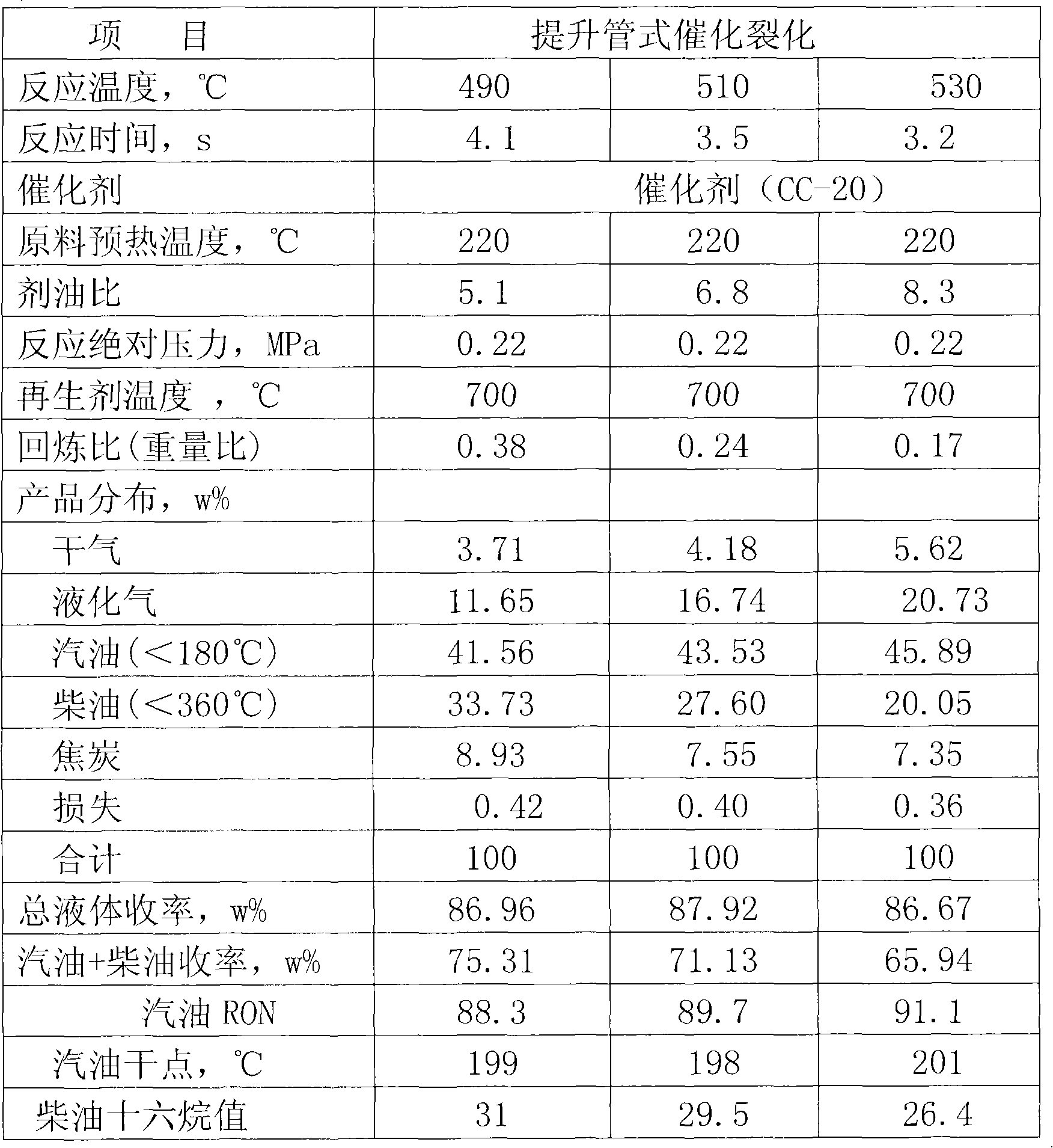
[0061] The raw material used in the test was atmospheric residual oil from Daqing, and the catalyst was commercially available CC-20 catalytic cracking industrial equilibrium catalyst with a microreactive activity of 65.

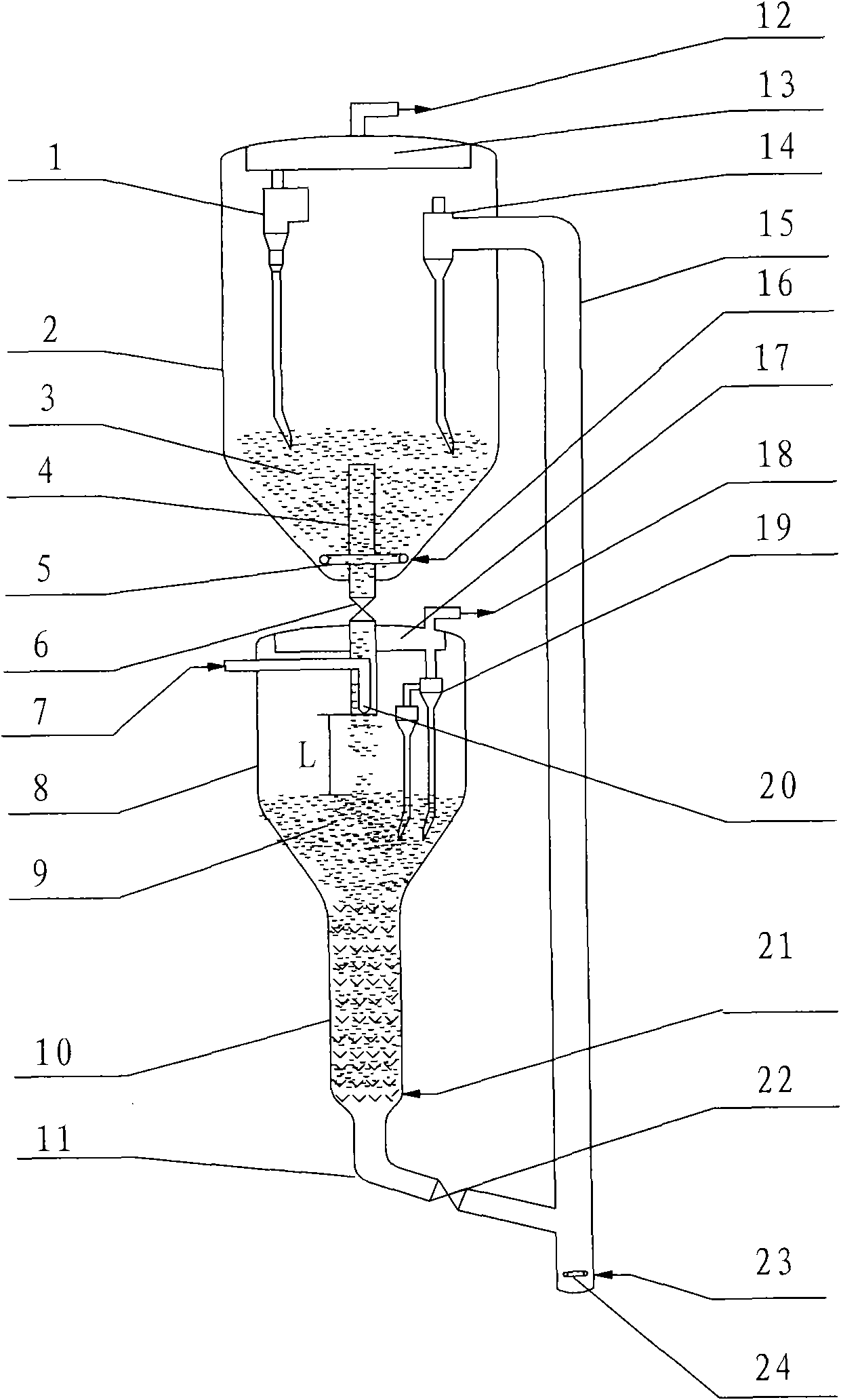
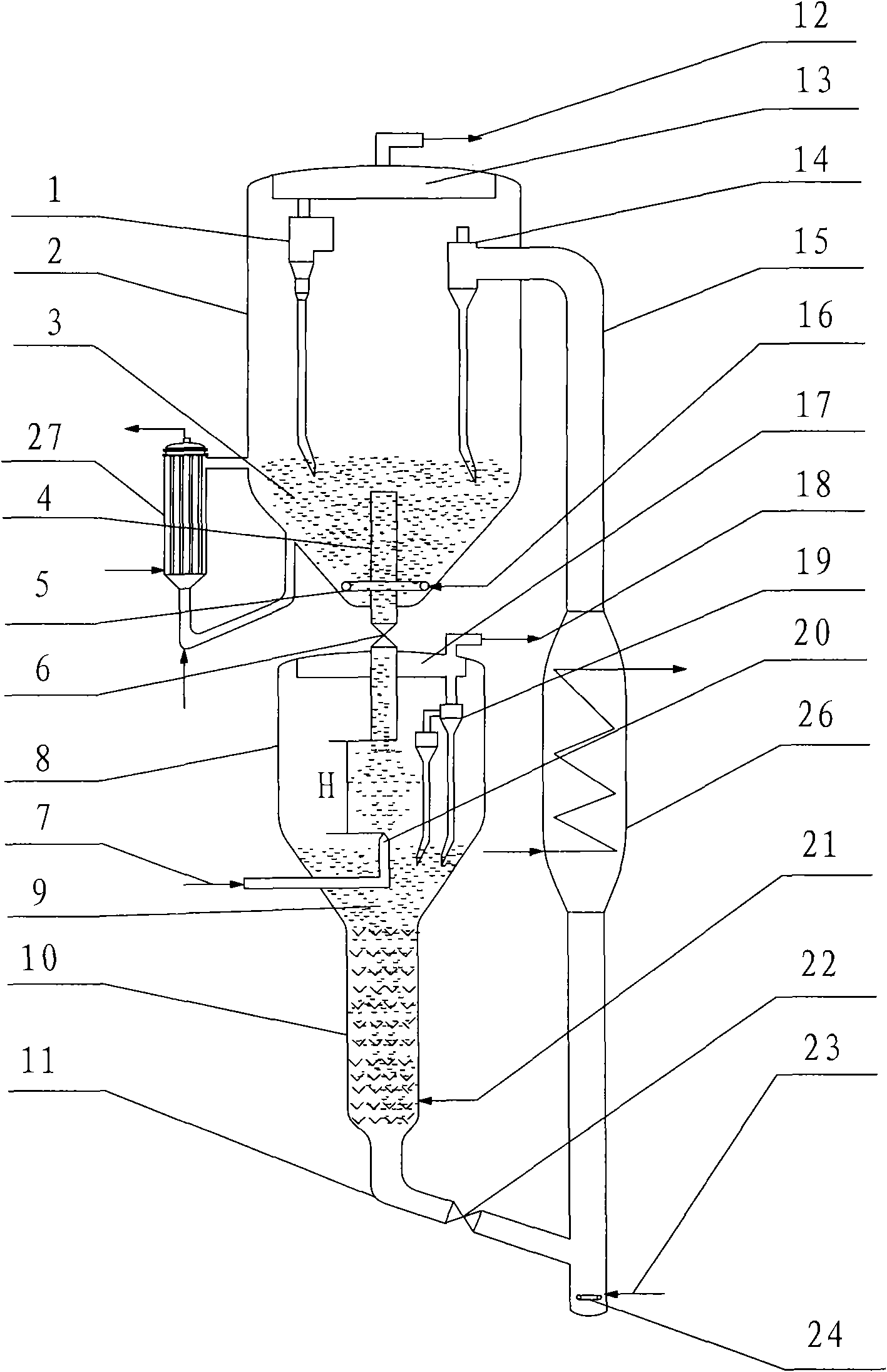
[0062] The short-range, high-efficiency catalytic cracking program is carried out on a small fluidized bed device in the laboratory. The ungenerated catalyst is burnt in a tubular manner and then enters the regenerator with a micro-reaction activity of 65. The stripping medium in the stripping section of the reaction settler is water vapor, and the stripping temperature is 500°C. The operating conditions, product distribution and some product properties of the short-range, high-efficiency catalytic cracking unit in this example are shown in Table 3.

Embodiment 2

[0064] According to Example 1, the difference is the temperature of the regenerated catalyst from the regenerator, the ratio of feedstock to oil in the reaction settler, and the reaction time. The operating conditions, product distribution and some product properties of the short-range, high-efficiency catalytic cracking unit in this example are shown in Table 4.

Embodiment 3

[0066] According to Example 1, the difference is the temperature of the regenerated catalyst from the regenerator, the ratio of feedstock to oil in the reaction settler, and the reaction time. The operating conditions, product distribution and some product properties of the short-range, high-efficiency catalytic cracking unit in this example are shown in Table 5.


PUM


Abstract

The invention discloses a catalytic cracking process and a catalytic cracking device. A main technical scheme is that: a regenerator is placed on the upper part of a reaction precipitator; a regenerated catalyst from the regenerator downwards enters the reaction precipitator to generate forward or backward contact reaction with raw oil entering the reaction precipitator through a feeding nozzle; after the reaction, the spent catalyst and the generated oil gas are subjected to separation and steam stripping; the generated oil gas subjected to separation and steam stripping enters a fractionating system to perform fractionation; the spent catalyst subjected to separation and steam stripping enters a tube type burning device to burn and regenerate; and the semi-regenerated catalyst regenerated by the tube type burning device enters a regenerator again to regenerate and then is recycled. By the catalytic cracking process and the catalytic cracking device, burning capacity can be enhanced and the treating quantity of raw materials is increased. The catalytic cracking process and the catalytic cracking device have the advantages of low contact temperature of the catalyst and the raw oil, short reaction time, big ratio of the catalyst to the oil, low yield of cracked gas and coke, high yield of gasoline and diesel, high product distributivity, simple device structure, operating flexibility, low energy consumption and the like.

Description

technical field [0001] The invention belongs to the field of catalytic cracking of hydrocarbon oil, in particular to a short-range, high-efficiency catalytic cracking process and device. Background technique [0002] At present, in the catalytic cracking process of the petrochemical industry, the top outlets of the riser reactors of the single or multiple riser catalytic cracking devices are respectively connected with the respective settlers, and the bottom is passed through the respective inclined pipes and standby The riser pipe communicates with the regenerator. In the above-mentioned conventional catalytic cracking unit, there are the following problems: first, the temperature of the regenerator cannot be flexibly controlled, and the regeneration temperature of the catalyst is generally higher than 650°C, which makes the instantaneous contact temperature of the oil agent in the riser reactor relatively high. High, too high oil agent contact temperature will increase th...

Claims


Application Information

Patent Timeline
Patent Type & Authority Patents(China)
IPC IPC(8): C10G11/18
Inventor 王文柯陈曼桥张亚西王龙延汤海涛孟凡东闫鸿飞
Owner CHINA PETROCHEMICAL CORP
Why Eureka
Try Eureka