Refrigerator

A refrigerator and cabinet technology, applied in the field of refrigerators, can solve problems such as troublesome daily use, large air flow resistance, and large energy loss, and achieve the effects of saving space, increasing ice production, and speeding up ice production

Inactive Publication Date: 2011-10-12
HEFEI MIDEA REFRIGERATOR CO LTD +1
View PDF10 Cites 12 Cited by
  • Summary
  • Abstract
  • Description
  • Claims
  • Application Information

AI Technical Summary

Problems solved by technology

[0002] Traditionally, refrigerators with an automatic ice-making system usually put the automatic ice-making system in the freezer, so that when using ice, the user needs to open the door of the freezer, and then bend down to take the ice, which is troublesome in daily use
In addition, there are also automatic ice-making systems arranged in the refrigerating room, which can realize penetrating ice extraction from the refrigerating door. However, since the automatic ice-making system occupies a large volume in the refrigerating room, the user can use the volume of the refrigerating room low rate
In addition, there is also an automatic ice-making system arranged on the door body to realize penetrating ice extraction through the door body. The ice-making system in the door body and the freezer and refrigerator compartments of the refrigerator are provided by a single evaporator located in the freezer. , the cooling capacity is sent to the refrigeration system through a long air duct, so the stroke of the air duct is longer, the air flow resistance generated is relatively large, and the energy loss is also relatively large, which affects the ice production volume and ice production speed. In addition, from The structure of the air duct in the freezer to increase the cooling capacity to the ice-making system in the door is complicated and difficult to realize

Method used


Image

  • Refrigerator
  • Refrigerator
  • Refrigerator

Examples


Embodiment Construction

[0025] Embodiments of the present invention are described in detail below, examples of which are shown in the drawings, wherein the same or similar reference numerals designate the same or similar elements or elements having the same or similar functions throughout. The embodiments described below by referring to the figures are exemplary only for explaining the present invention and should not be construed as limiting the present invention.

[0026] In describing the present invention, it should be understood that the terms "center", "longitudinal", "transverse", "upper", "lower", "front", "rear", "left", "right", " The orientations or positional relationships indicated by "vertical", "horizontal", "top", "bottom", "inner", "outer", etc. are based on the orientation or positional relationships shown in the drawings, and are only for the convenience of describing the present invention and simplifying Describes, but does not indicate or imply that the device or element referred...


PUM


Abstract

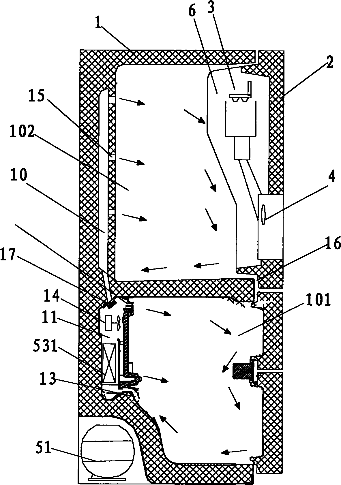
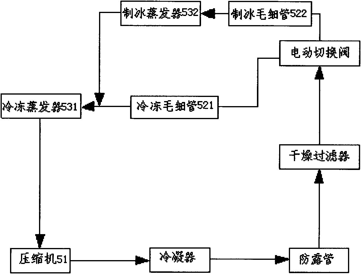
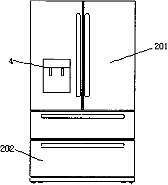
The invention discloses a refrigerator, which comprises a refrigerator body, a door body, an ice-making device, a distributor and a refrigeration system, wherein a freezing chamber and a refrigerating chamber are defined in the refrigerator body; the door body is used for opening and closing the freezing chamber and the refrigerating chamber; an ice-making chamber is defined in the door body; the ice-making device is arranged in the ice-making chamber; the distributor is arranged in the door body and exposed from the door body; the distributor is connected with the ice-making device and used for distributing ice cakes; the refrigeration system comprises a compressor, a condenser, a capillary tube and an evaporator, which are connected with one another sequentially; the evaporator comprises a freezing evaporator and an ice-making evaporator; the freezing evaporator is used for refrigerating the freezing chamber and the refrigerating chamber; and the ice-making evaporator is arranged in the door body and used for refrigerating the ice-making chamber. According to the refrigerator provided by the embodiment of the invention, the ice-making device has an independent ice-making evaporator, so an ice-making speed is greatly improved, ice-making capacity is improved, structure is simple, and refrigeration loss is avoided.

Description

technical field [0001] The invention relates to the technical field of refrigeration, in particular to a refrigerator. Background technique [0002] Traditionally, refrigerators with an automatic ice-making system usually put the automatic ice-making system in the freezer compartment, so that when using ice cubes, the user needs to open the freezer compartment door and then bend down to take the ice, which is troublesome in daily use. In addition, there are also automatic ice-making systems arranged in the refrigerating room, which can realize penetrating ice extraction from the refrigerating door. However, since the automatic ice-making system occupies a large volume in the refrigerating room, the user can use the volume of the refrigerating room The rate is low. In addition, there is also an automatic ice-making system arranged on the door body to realize penetrating ice extraction through the door body. The ice-making system in the door body and the freezer and refrigera...

Claims


Application Information

Patent Timeline
Patent Type & Authority Applications(China)
IPC IPC(8): F25D11/02F25D17/06F25D19/00F25D23/02F25D23/12F25C1/00F25B41/06
Inventor 刘东现李凌云程建任伟
Owner HEFEI MIDEA REFRIGERATOR CO LTD
Why Eureka
Try Eureka