Tempering Furnace

A tempering furnace and furnace body technology, which is applied in the field of tempering furnaces, can solve the problems of easy deformation, high production cost, and large temperature deviation range in the furnace, so as to reduce heat loss, enhance heat utilization, and improve fuel utilization. Effect

Active Publication Date: 2011-10-12
LISHUI HUAYI AUTOMATION TECH
View PDF7 Cites 11 Cited by
  • Summary
  • Abstract
  • Description
  • Claims
  • Application Information

AI Technical Summary

Problems solved by technology

The current tempering furnace is mainly a horizontal tempering furnace, but for some workpieces with long dimensions and high precision requirements, such as linear slide rails, the horizontal tempering workpiece is easy to deform, which seriously affects the tempering quality of the workpiece , so most of these workpieces are tempered in pit tempering furnaces
[0003] At present, when the well-type tempering furnaces on the market are used, the workpieces are directly placed in the furnace for tempering without special structural devices to clamp the workpieces. Uneven heating directly affects tempering quality
Most of the tempering furnaces currently on the market do not have a hot air circulation system. These tempering furnaces have poor temperature uniformity, a wide range of temperature deviations in the furnace, cumbersome operations, high production costs, and cannot meet the heat treatment needs of high-precision products.

Method used


Image

  • Tempering Furnace
  • Tempering Furnace
  • Tempering Furnace

Examples


Embodiment Construction

[0019] The present invention will be further described below in conjunction with accompanying drawing:

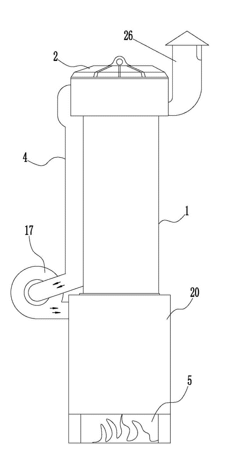
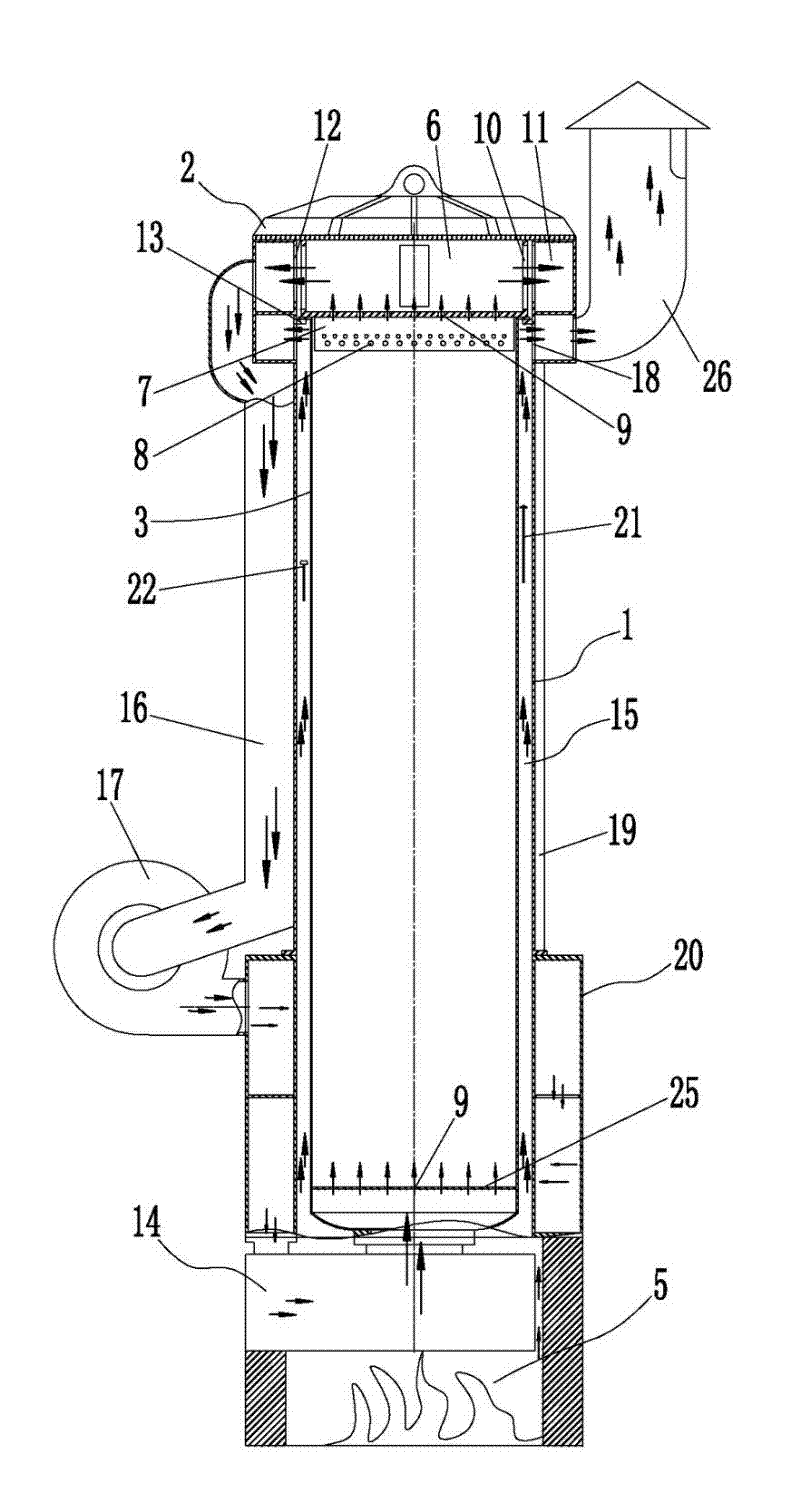
[0020] Referring to the accompanying drawings: this tempering furnace in the present embodiment includes a furnace body 1, a furnace cover 2 is provided at the top of the furnace body 1, an inner container 3 is provided in the furnace body 1, and an air circulation heating device 4 is provided on the furnace body 1 , the bottom end of the furnace body 1 is provided with a furnace 5,

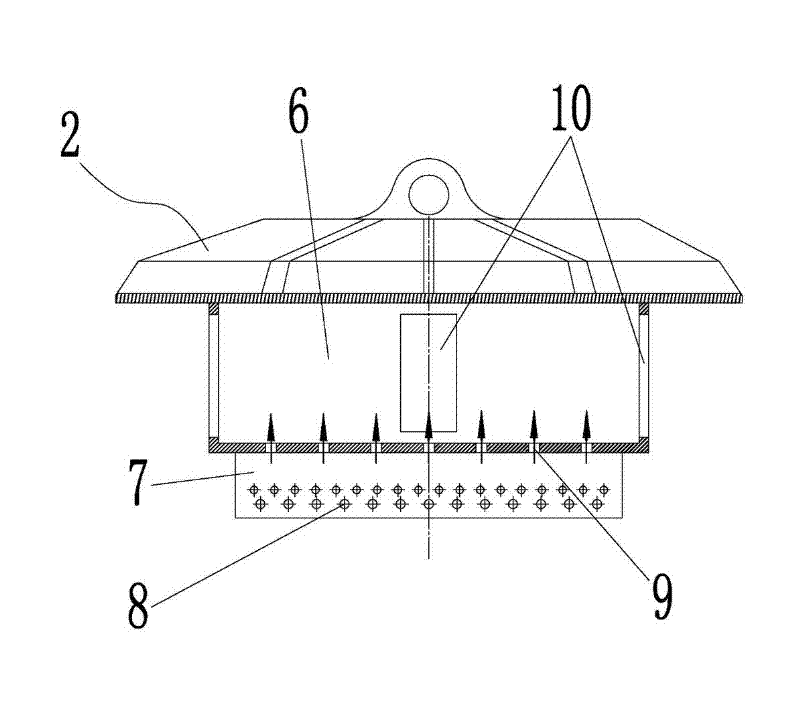
[0021] A cavity 6 is provided inside the lower end of the furnace cover 2, and the bottom end surface of the furnace cover 2 is sealed and connected with the opening of the inner tank 3. A group of steel plates 7 with pin holes 8 are arranged on the bottom end surface of the furnace cover 2, and the pins on each steel plate 7 The holes 8 are matched with each other, the pin hole 8 is pierced with a pin rod 27, a group of ventilation holes 9 are opened on the bottom surface of the furnace cover...


PUM


Abstract

The invention relates to a tempering furnace. The furnace comprises a furnace body, the top of which is provided with a furnace cover, an inner container is arranged in the furnace body, an air circulating and heating device is arranged on the furnace body, and a hearth is arranged at the bottom end of the furnace body. By properly arranging the furnace cover, the inner container, the air circulating and heating device and the like, the tempering furnace provided by the invention achieves omidirectional tempering of a workpiece which is suspended below the furnace cover by the process of uniformly heating, cycling and preheating the gas in the furnace, thus avoiding tempering blind spot in the furnace, obviously decreasing the temperature deviation in the furnace, and effectively improving the tempering quality of the workpiece in the furnace. Moreover, the tempering furnace maximally utilizes the heat created by burning the fuel, and further improves the furnace tempering effect. The tempering furnace of the invention has the advantages of reasonable and simple structure, low production cost, simplicity of operation, convenience of maintenance, high efficiency and energy conservation, and is suitable for popularization.

Description

technical field [0001] The invention relates to heat treatment equipment, in particular to a tempering furnace. Background technique [0002] With the development of science and technology and the continuous improvement of production equipment, people's requirements for heat treatment technology are also getting higher and higher, and then the requirements for heat treatment equipment are also getting higher and higher. The current tempering furnace is mainly a horizontal tempering furnace, but for some workpieces with long dimensions and high precision requirements, such as linear slide rails, the horizontal tempering workpiece is easy to deform, which seriously affects the tempering quality of the workpiece , so most of these workpieces are tempered in a well-type tempering furnace. [0003] At present, when the well-type tempering furnaces on the market are used, the workpieces are directly placed in the furnace for tempering without special structural devices to clamp t...

Claims


Application Information

Patent Timeline
Patent Type & Authority Applications(China)
IPC IPC(8): F27B1/00C21D1/00
Inventor 郑金彩
Owner LISHUI HUAYI AUTOMATION TECH
Why Eureka
Try Eureka