Cooling device for internal combustion engine
A technology of cooling device and internal combustion engine, which is applied in the direction of engine cooling, internal combustion piston engine, liquid cooling, etc., can solve the problems of increased fuel consumption, worsening emission, etc., and achieve the effect of suppressing temperature reduction, reducing surface area, and being easy to manufacture.
- Summary
- Abstract
- Description
- Claims
- Application Information
AI Technical Summary
Problems solved by technology
Method used
Image

Examples
Embodiment approach 1
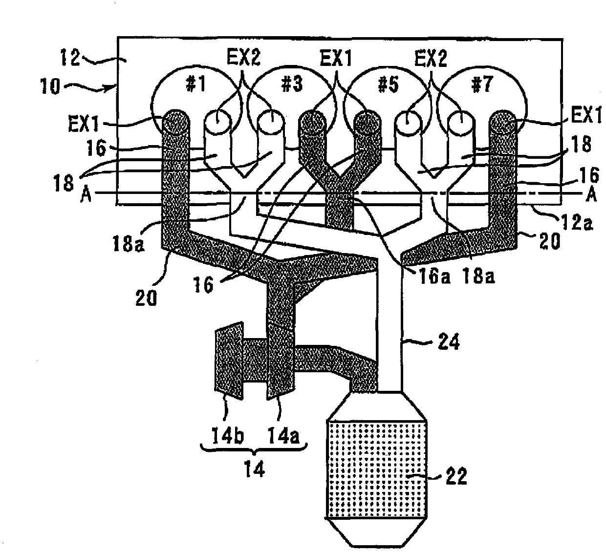
[0063] figure 1 It is a schematic plan view for explaining the exhaust system of the internal combustion engine according to Embodiment 1 of the present invention. In addition, in figure 1 In , the number with # indicates the cylinder number.
[0064] figure 1 The internal combustion engine 10 of the present embodiment shown is a V-type 8-cylinder internal combustion engine, but in figure 1 Only the one-sided series consisting of No. 1, No. 3, No. 5 and No. 7 are shown in . However, in the present invention, the number of cylinders and cylinder arrangement of the internal combustion engine 10 are not limited thereto.
[0065] The internal combustion engine 10 includes a turbocharger 14 having a turbine 14a and a compressor 14b. The turbine 14a is operated by the energy of the exhaust gas. The compressor 14b is driven by the turbine 14a to compress the intake air.
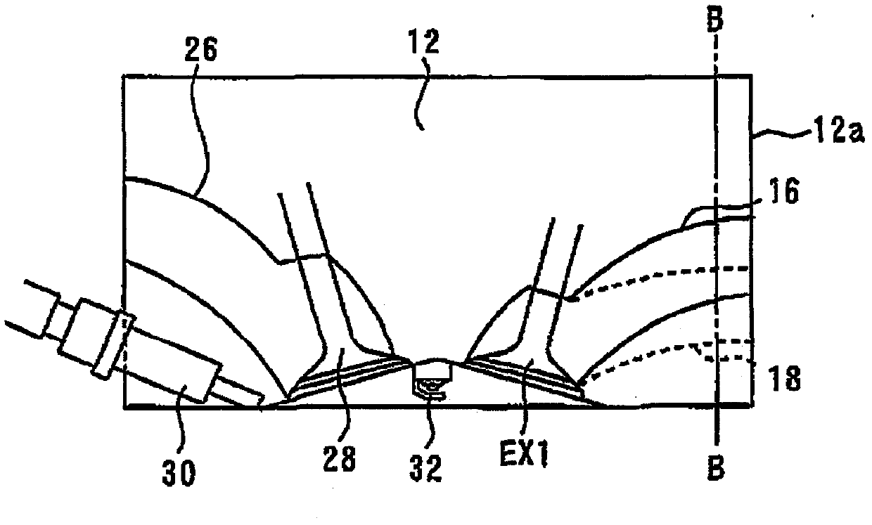
[0066] The cylinder head 12 of the internal combustion engine 10 is respectively formed with a turbine-sid...
Embodiment approach 2
[0081] Next, refer to Figure 5 to Figure 8 Embodiment 2 of the present invention will be described, but the description will focus on the points that are different from the above-mentioned Embodiment 1, and the description of the same matters will be simplified or omitted.
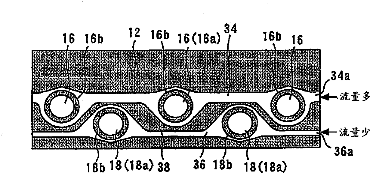
[0082] Figure 5 It is a sectional view of the cylinder head 12 of the internal combustion engine 10 according to Embodiment 2 of the present invention. Such as Figure 5 As shown, in the present embodiment, a flow rate control valve 40 is provided in the middle of the flow path toward the inlet 34 a of the first cooling water passage 34 . By adjusting the opening degree of the flow control valve 40, the ratio of the cooling water flow rates of the first cooling water passage 34 and the second cooling water passage 36 can be changed and adjusted to a target ratio. In the following description, the ratio of the cooling water flow rate of the first cooling water passage 34 to the total cooling water flow...
Embodiment approach 3
[0102] Next, refer to Figure 9 to Figure 12 Embodiment 3 of the present invention will be described, but the description will focus on points that are different from the above-mentioned embodiment, and the description of the same items will be simplified or omitted.
[0103] In Embodiment 2 described above, control is performed such that the higher the turbine-side exhaust gas ratio is, the higher the turbine-side cooling water ratio is. Therefore, also in the high load region where the turbine-side exhaust gas ratio becomes high, it is possible to more reliably prevent the excessive temperature rise of the turbine-side exhaust port 16 and the turbine casing.
[0104] However, when a request for acceleration exceeding a predetermined limit (hereinafter referred to as "sudden acceleration") is detected, such as when the accelerator opening is suddenly increased, it is desirable to increase the amount of exhaust gas flowing into the turbocharger 14 as much as possible in order ...
PUM
 Abstract
Description
Claims
Application Information
 - R&D
- Intellectual Property
- Life Sciences
- Materials
- Tech Scout
- Unparalleled Data Quality
- Higher Quality Content
- 60% Fewer Hallucinations
Browse by: Latest US Patents, China's latest patents, Technical Efficacy Thesaurus, Application Domain, Technology Topic, Popular Technical Reports.
© 2025 PatSnap. All rights reserved.Legal|Privacy policy|Modern Slavery Act Transparency Statement|Sitemap|About US| Contact US: help@patsnap.com