
Double-runner cone valve

A technology of cone valve and double flow channel, which is applied in the direction of lifting valve, valve device, engine components, etc., can solve the problems affecting the volume coefficient of the pump (volume efficiency, increase the manufacturing cost, large vibration and noise, etc., and achieve the improvement of volume coefficient, Strong flow capacity, low vibration and noise of the pump valve

Active Publication Date: 2012-10-03
NINGBO HELI MECHANICAL PUMP CO LTD
View PDF0 Cites 0 Cited by
  • Summary
  • Abstract
  • Description
  • Claims
  • Application Information

AI Technical Summary

Problems solved by technology

) If the valve plate is not closed in time, the backflow of high-pressure liquid will occur, which will affect the volume coefficient (volume efficiency) of the pump
[0005] 2. When the valve plate is at the hysteresis height position, the valve plate is closed under the action of reverse high pressure, which will inevitably produce greater vibration and noise
[0006] 3. The pump valve works under the condition of frequent opening and closing, and the frequency is very high. The kinetic energy formed by the closing speed of the pump valve and its mass will cause an impact at the moment when the valve plate is closed.
If the closing speed of the valve plate is constant, the greater the mass of the valve plate, the greater the impact energy will be, which will accelerate the damage of the pump valve over time.
[0007] 4. The increase in the size of the pump valve will inevitably increase the size of the pump body, various connectors, and fasteners, which will inevitably increase the manufacturing cost

Method used


Image

  • Double-runner cone valve
  • Double-runner cone valve
  • Double-runner cone valve

Examples


Embodiment Construction

[0028] The present invention will be further described in detail below in conjunction with the accompanying drawings and embodiments.

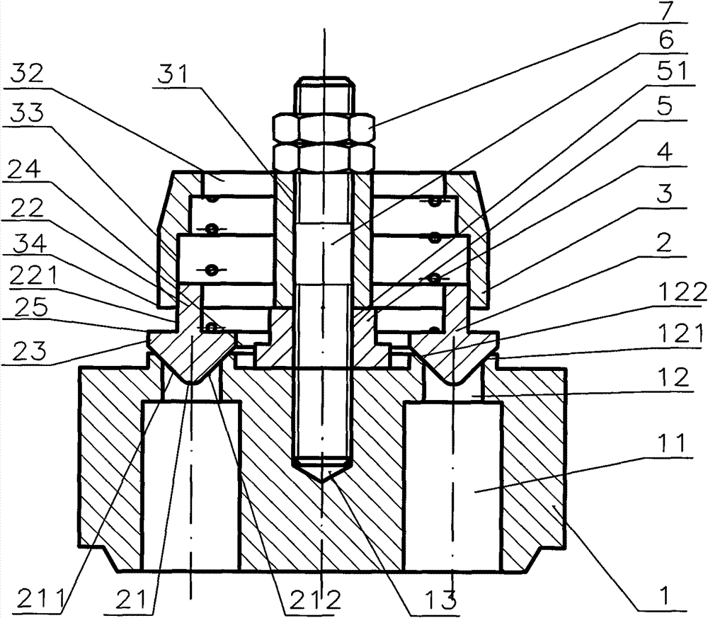
[0029] See figure 1 As shown, the lower part of the valve seat 1 of the double-channel conical valve of the present invention has a plurality of non-penetrating holes 11 evenly distributed in the circumferential direction, and an annular groove 12 is formed on the upper part, and the annular groove 12 communicates with the lower hole 11 of the valve seat, and The central circumference lines of the two coincide. The mouth of the annular groove 12 is designed as a tapered mouth narrowed at the bottom, and its two annular surfaces 121, 122 form an included angle of 45° with the upper plane of the valve seat, so that the two planes at the upper end of the annular flow channel of the valve seat 1 form a 90° included angle. There is a threaded hole 13 in the center of the valve seat 1, which can be used for screw connection.

[0030] The valve p...


PUM


Abstract

The invention relates to a double-runner cone valve mainly comprising a valve seat. An annular groove communicated with a lower part hole is arranged at the upper part of the valve seat, and the mouth part of the annular groove is designed to be a conical mouth with a narrowing lower part; an annular conical bulge, suitable for opening and closing the conical mouth of the valve seat, is arranged at the lower part of the valve seat; a valve cover is sheathed on a valve plate and is matched with the valve plate is a sliding way, a space for the valve plate to move upwards is arranged between the valve plate and the valve cover, and the valve cover is internally provided with a spring; and a screw rod penetrates through the valve cover, the valve plate and a central hole of an adjusting barrel so as to fix the valve cover, the valve plate and the central hole with the valve seat. The double-runner cone valve has the advantages that the sealing performance is good, the bearing pressure ishigh, the size is small, the area of the space is large, the flow of overflowing is large, and the like.

Description

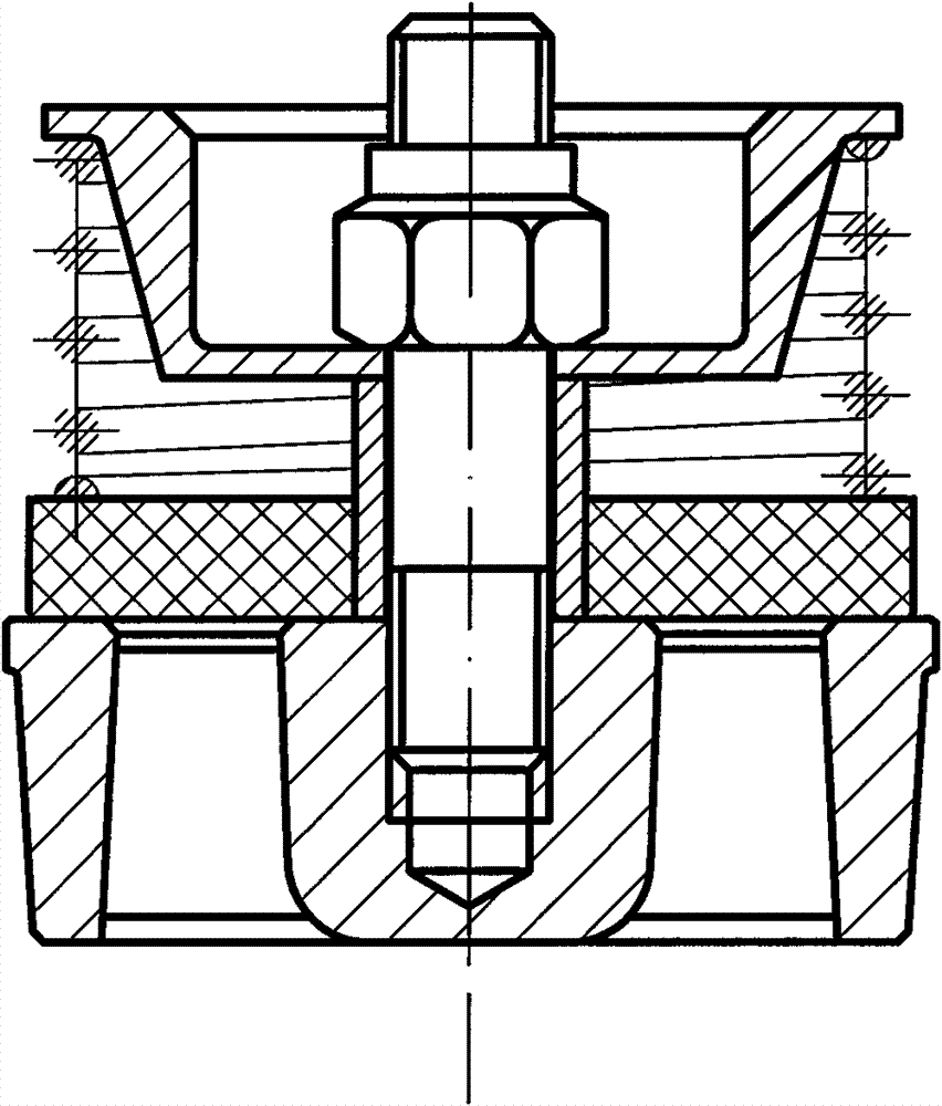
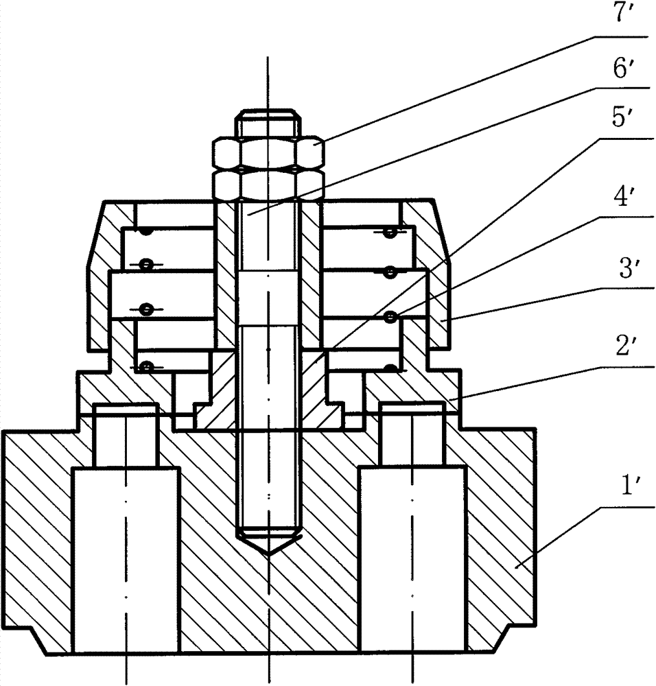
technical field [0001] The invention relates to a double-channel cone valve. Background technique [0002] Pump valves are key components of reciprocating pumps. Pump valves mostly use automatic valves that are closed by spring force. Flat valves and cone valves are widely used in automatic valves. Common plate valves such as figure 2 According to the results, the flat valve is widely used to transport water at room temperature, low viscosity oil or medium similar to clean water. It has a simple structure and is easy to manufacture, but its sealing performance is not as good as that of the cone valve, and it is mostly used for pumps with low discharge pressure. Appropriately changing the structure of the flat valve can evolve into a ring valve. Such as image 3 As shown, the annular valve is mainly composed of a valve seat 1', a valve plate 2', a valve cover 3', a spring 4', a screw sleeve 5', a valve stem 6', and a nut 7'. The outer circle of the upper part of the val...

Claims


Application Information

Patent Timeline
Patent Type & Authority Patents(China)
IPC IPC(8): F16K1/38F16K1/42F16K1/54
Inventor 陈明海龚名光
Owner NINGBO HELI MECHANICAL PUMP CO LTD
Learn More