Wing-shaped film hole of hot end component of aeroengine and electrode

A technology for aero-engines and hot-end components, which is applied in the direction of engine components, machines/engines, mechanical equipment, etc., can solve the problems of large gas and cold gas aerodynamic mixing loss, small gas film coverage area, complex processing technology, etc., and achieve good results Aerodynamic efficiency, good heat insulation effect, high flow coefficient effect

Active Publication Date: 2018-02-23
AECC HUNAN AVIATION POWERPLANT RES INST
View PDF6 Cites 5 Cited by
  • Summary
  • Abstract
  • Description
  • Claims
  • Application Information

AI Technical Summary

Problems solved by technology

[0012] The invention provides an airfoil air film hole and an electrode of the hot end part of an aero-engine to solve the gas film cooling of the existing aero-engine hot end part, and to cover the covered area of ​​the air film formed by spraying high-temperature gas from the air film hole Small, limited heat insulation effect; large loss of aerodynamic mixing of gas and cold air, complex processing technology, low processing efficiency technical problems

Method used


Image

  • Wing-shaped film hole of hot end component of aeroengine and electrode
  • Wing-shaped film hole of hot end component of aeroengine and electrode
  • Wing-shaped film hole of hot end component of aeroengine and electrode

Examples


Embodiment Construction

[0032] The embodiments of the present invention will be described in detail below with reference to the accompanying drawings, but the present invention can be implemented in various ways defined and covered below.

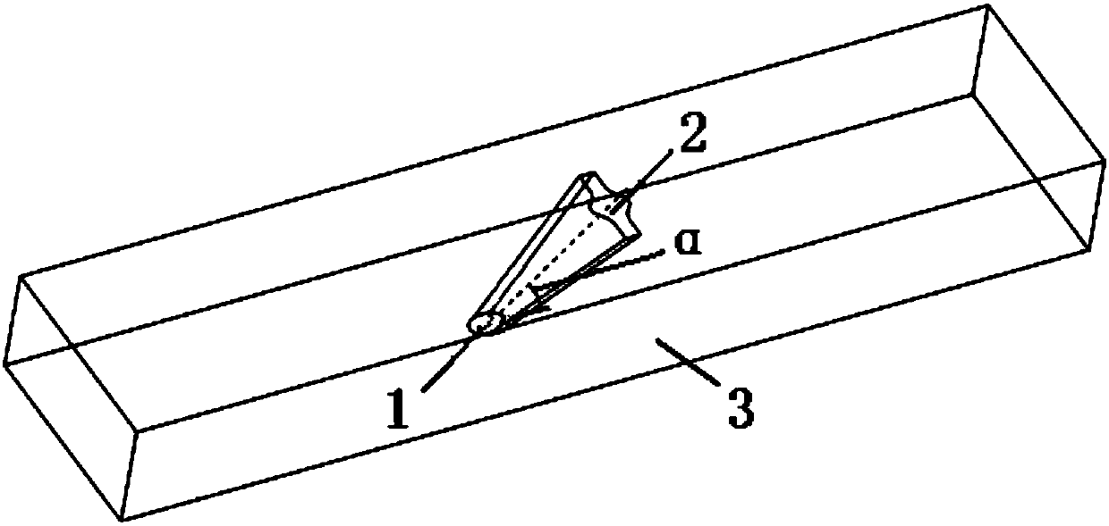
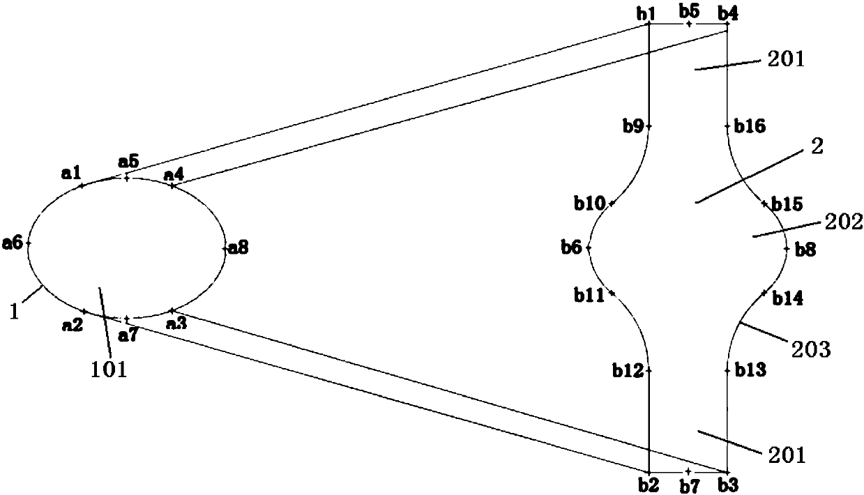
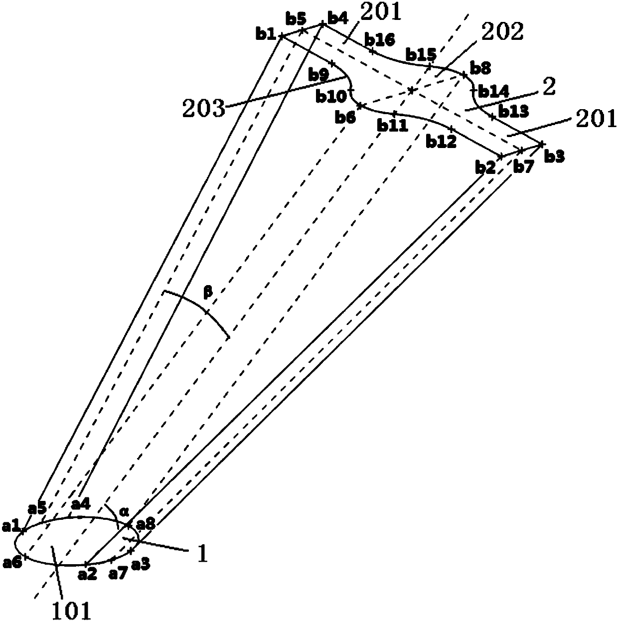
[0033] figure 1 It is a structural schematic diagram of the airfoil air film hole of the hot end part of the aero-engine in the preferred embodiment of the present invention; figure 2 It is a top view structural diagram of the airfoil air film hole of the hot end part of the aero-engine in the preferred embodiment of the present invention; image 3 It is a side view structure schematic diagram of the airfoil air film hole of the hot end part of the aero-engine in the preferred embodiment of the present invention; Figure 4 It is a structural schematic diagram of the electrode used for processing the airfoil air film hole of the hot end part of the aero-engine according to the preferred embodiment of the present invention.

[0034] Such as figure 1 and figure...


PUM


Abstract

The invention discloses a wing-shaped film hole of a hot end component of an aeroengine and an electrode. The wing-shaped film hole of the hot end component of the aeroengine comprises a cold air inlet and a cold air outlet. A central hole shaft of the wing-shaped film hole inclines relative to the wall of the hot end component, and the included angle between the central hole shaft of the wing-shaped film hole and the hot end component is alpha. The span direction of the wing-shaped film hole is increased gradually from the cold air inlet to the cold air outlet, and the thickness of the wing-shaped film hole is decreased gradually from the cold air inlet to the cold air outlet, so that cold air flowing into the wing-shaped film hole from the cold air inlet gradually spreads towards the twosides and flows closely along the outer surface of the hot end component outside the cold air outlet after being sprayed out in a decelerated mode from the cold air outlet which becomes thinner gradually. On the one hand, the cold air can easy flow closely along the wall surface of the hot end component after being sprayed out from the cold air outlet; and on the other hand, the cold air is mixedinto high-temperature fuel gas at a low speed, the pneumatic mixing loss of the fuel gas and the cold air is reduced, and the pneumatic efficiency of turbine blades is improved. The wing-shaped filmhole of the hot end component of the aeroengine and the electrode are easy to manufacture and machine and high in efficiency.

Description

technical field [0001] The invention relates to the technical field of machining hot-end parts of an aero-engine, in particular to an airfoil air film hole of a hot-end part of an aero-engine. In addition, the invention also relates to an electrode for machining the airfoil air film hole of the hot end part of the aero-engine. Background technique [0002] In an aero-engine, the hot-end components mainly rely on convective heat exchange with cold air to achieve cooling. For this reason, various measures must be taken to enhance heat transfer or block hot gas from heating the hot-end components to achieve less cooling air consumption and better cooling effects. Purpose. The advanced cooling scheme is an effective method to ensure the stable and reliable operation of the hot end components. In practical applications, the basic cooling methods mainly include: convective cooling, impingement cooling, divergent cooling and film cooling, among which film cooling has been widely u...

Claims


Application Information

Patent Timeline
Patent Type & Authority Applications(China)
IPC IPC(8): F01D5/18
CPCF01D5/186
Inventor 王漳军贺宜红孙瑞嘉谢昌坦李洋
Owner AECC HUNAN AVIATION POWERPLANT RES INST
Why Eureka
Try Eureka