Surge-preventing structure for aero-engine compressor

A technology of aero-engine and air compressor, which is applied in the direction of machines/engines, liquid fuel engines, mechanical equipment, etc. It can solve the problems of three-rotor structure, supporting force transmission, complicated lubrication, high cost and so on, and achieve the expansion of stable working range and low cost Effect of low, axial velocity and increased flow coefficient

Active Publication Date: 2013-04-17
HARBIN DONGAN ENGINE GRP
View PDF7 Cites 5 Cited by
  • Summary
  • Abstract
  • Description
  • Claims
  • Application Information

AI Technical Summary

Problems solved by technology

The structure, support, force transmission and lubrication of the three rotors are all complicated, and the cost is high

Method used


Image

  • Surge-preventing structure for aero-engine compressor

Examples


Embodiment Construction

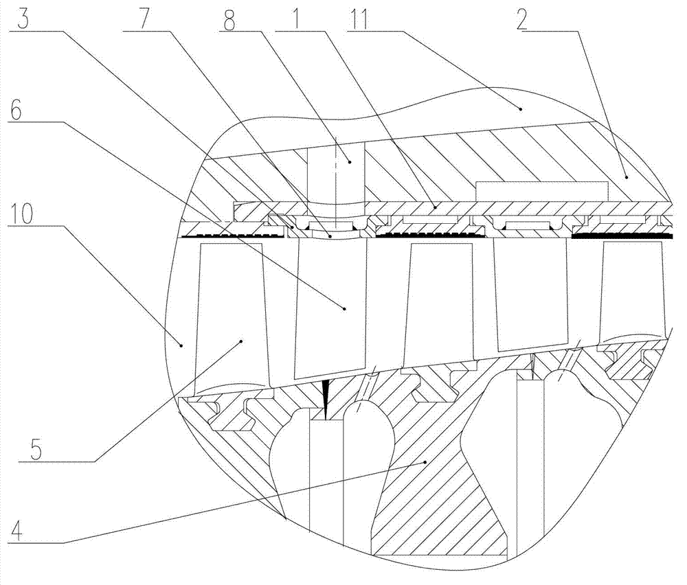
[0008] As shown in the figure, the anti-puff structure of an aero-engine compressor includes a compressor casing 1, an intermediate casing 2, and a stator ring 3. The intermediate casing 2 is installed on the compressor casing 1, and the stator ring 3 is installed inside the compressor casing 1. , the stator ring 3 is provided with stator blades 6 evenly distributed in the circumferential direction, the compressor rotor 4 is located in the compressor casing 1 and is equipped with rotor blades 5, the rotor blades 5 and the stator blades 6 are interlaced to form an inner channel 10, and the intermediate casing 2 The outside is the outer duct 11, which is located at the position of the stator vanes 6 on the stator ring 3. There are radial vent holes 7 in the middle of every two stator vanes 6, and there are holes in the corresponding positions on the compressor casing 1 and the intermediate casing. The diameter is greater than the air release hole 8 of the radial air release hole ...


PUM


Abstract

The invention relates to a surge-preventing structure for an aero-engine compressor. A stator ring is mounted inside a compressor case, uniformly and peripherally distributed stator vanes are arranged on the stator ring, a compressor rotor is positioned inside the compressor case 1 and is provided with rotor vanes, a radial vent hole is reserved between each two stator vanes and at the peripheral position of the stator vanes on the stator ring, and vent holes with the diameter larger than that of each radial vent hole are reserved at the corresponding positions on an intermediate case and the compressor case. Speed loss and surge due to overlarge attack angles are eliminated; and flow condition is improved, thereby surge can be prevented effectively. The surge-preventing structure has the advantages that compressor characteristics can be improved, stable working range can be widened, and the surge-preventing structure can be used for preventing 'front-surge and rear-vortex' type surges and is convenient to process, low in size required accuracy, simple, low in cost and reduced in gas loss.

Description

technical field [0001] The invention relates to an anti-puff structure of an aero-engine compressor. Background technique [0002] When the multi-stage axial flow compressor of an aero-engine works under variable working conditions, when the inlet flow decreases, the angle of attack is positive, and the air flow will be separated on the back side of the blade. In this area, once the separation occurs, there will be continuous The trend of development continues, therefore, the excessive positive attack angle can make the operation of the compressor unstable, thus causing surge. When the engine speed is lower than the design speed, the first few stages of compressors will surge due to the excessive angle of attack, while the angle of attack in the last stage will decrease, and the pressure rise and efficiency will decrease rapidly. When the operating conditions deviate greatly from the designed operating conditions , the pressure rise value of the final stage is likely to bec...

Claims


Application Information

Patent Timeline
Patent Type & Authority Applications(China)
IPC IPC(8): F04D29/66
Inventor 陶江王学斌陈玉英贺健孙先超罗玉权
Owner HARBIN DONGAN ENGINE GRP
Why Eureka
Try Eureka