Flood discharge structure adopting bottom hole and surface hole combined flood discharge and energy dissipation

A flood discharge structure and flood discharge technology, applied in marine engineering, construction, barrage/weir, etc., can solve the problems of water flow directly scouring the downstream river bank, the influence of the stability of the downstream bank slope, and low energy dissipation rate, so as to increase the energy dissipation rate and flow rate. The effect of coefficient, reduction of digging depth, reduction of impact strength

Active Publication Date: 2021-01-29
WUHAN UNIV
View PDF6 Cites 5 Cited by
  • Summary
  • Abstract
  • Description
  • Claims
  • Application Information

AI Technical Summary

Problems solved by technology

Bottom current energy dissipation is mainly achieved through hydraulic jumps, but when the incoming flow's Freund's number is small, its energy dissipation rate is relatively low, and the water flow is easy to directly scour the downstream river bank, which has a great impact on the stability of the downstream bank slope

Method used


Image

  • Flood discharge structure adopting bottom hole and surface hole combined flood discharge and energy dissipation
  • Flood discharge structure adopting bottom hole and surface hole combined flood discharge and energy dissipation
  • Flood discharge structure adopting bottom hole and surface hole combined flood discharge and energy dissipation

Examples


Embodiment Construction

[0020] The present invention will be further described below in conjunction with the embodiments shown in the accompanying drawings.

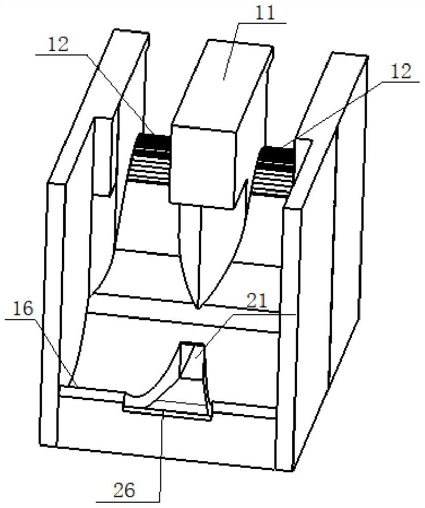
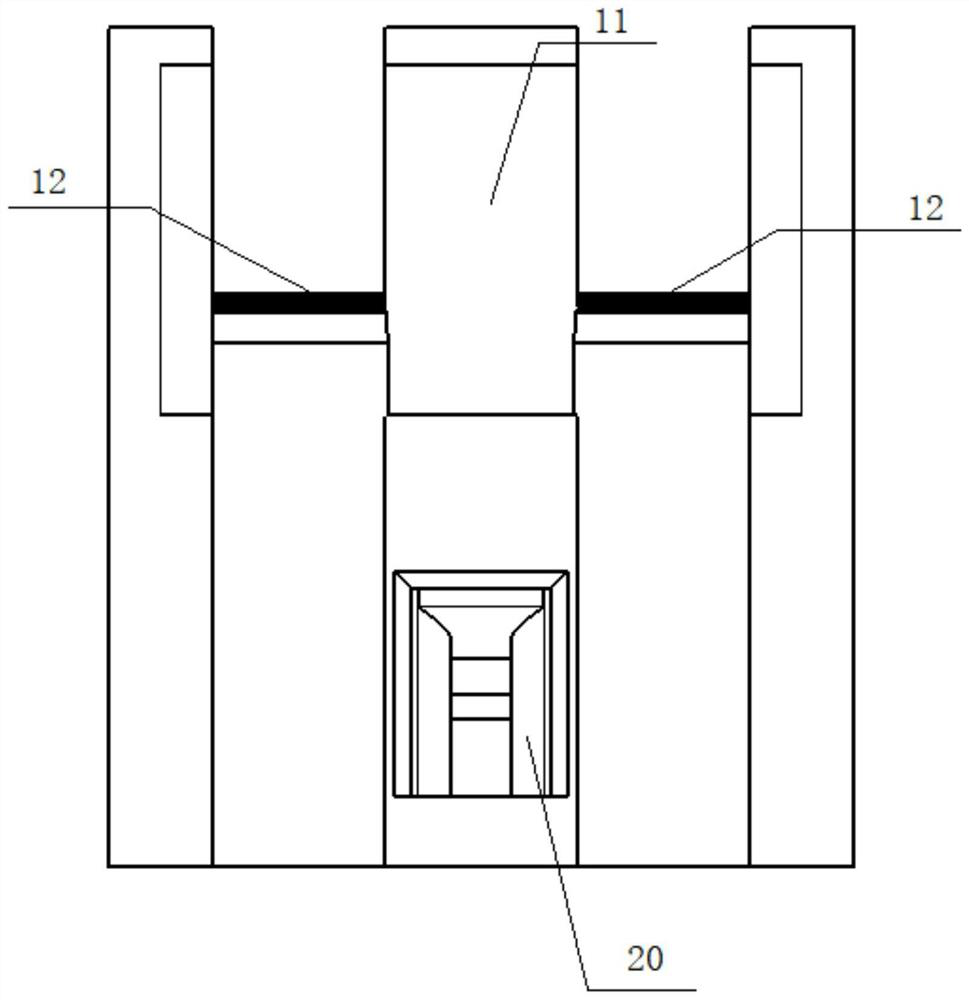
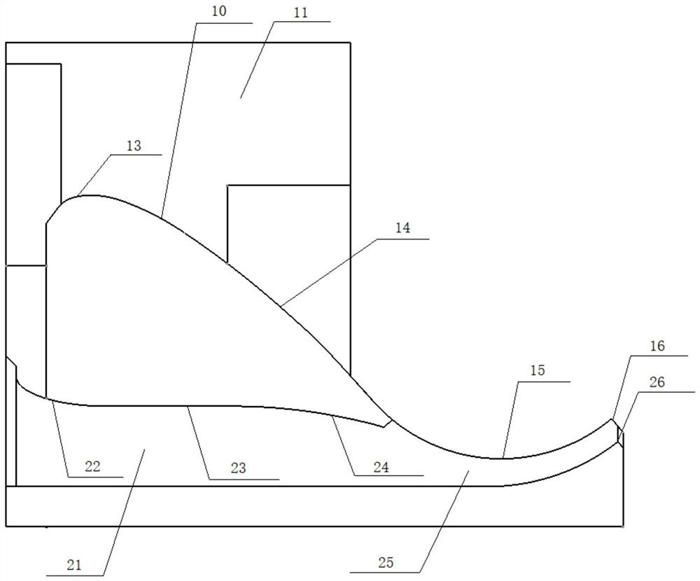
[0021] as attached Figures 1 to 3 As shown, this embodiment discloses a flood discharge building, which is used as a water conservancy and hydropower project for flood discharge and energy dissipation. It has a flood discharge structure that uses a combination of bottom holes and surface holes. The method improves the energy dissipation rate in the stilling pool, and can significantly reduce the scouring effect of the discharged water on the bank slope.

[0022] Specifically, such as figure 1 and 2 As shown, the flood discharge structure includes: a surface hole flood discharge unit 10 and a bottom hole flood discharge unit 20, which are arranged in sequence from top to bottom along the vertical direction of the flood discharge building, so that when the flood discharge flow is small, only the bottom hole is used for flood discharge. The un...


PUM


Abstract

The invention provides a flood discharge structure adopting bottom hole and surface hole combined flood discharge and energy dissipation. The flood discharge structure comprises a surface hole and a bottom hole, wherein the surface hole and the bottom hole are formed in sequence from top to bottom in a vertical direction, the surface hole comprises a wide pier which is arranged in the middle and overflow surface holes which are formed in both sides of the wide pier, the bottom hole comprises a flood discharge bottom hole which is formed in the middle below the surface hole, and an outlet of the flood discharge bottom hole is located in a connected area of the two overflow surface holes. The overflow surface holes and the flood discharge bottom hole are formed in a combined mode from top tobottom in the vertical direction; when the discharge amount is small, only the bottom hole is opened so as to discharge water; and when the discharge capacity is large, the overflow surface holes andthe flood discharge bottom hole are opened at the same time so as to discharge flood, and the energy dissipation rate and the flow coefficient are increased. Water flow from the surface and bottom holes collides in the air, the nappe transversely diffuses, energy is dissipated, the impact strength on a stilling pool is reduced, and the digging depth can be correspondingly reduced; and additionally, the longitudinal length of the nappe is reduced, and the length of the stilling pool can be correspondingly reduced. Therefore, the flood discharge structure and the stilling pool are compact in arrangement and are convenient to manage, and the engineering investment is saved.

Description

technical field [0001] The invention belongs to the technical field of flood discharge and energy dissipation in water conservancy and hydropower projects, and in particular relates to a flood discharge structure that adopts a combined flood discharge and energy dissipation through a bottom hole and a surface hole. Background technique [0002] A large number of small and medium-sized sluice dams, overflow dams and other water conservancy and hydropower projects are generally built in the middle and lower reaches of rivers in our country. However, these projects are often limited by the flood discharge width due to the influence of the topography and geology of the dam site. Therefore, the single-width discharge of the flood discharge and flow-through buildings will be relatively large, and these water conservancy projects generally have low water heads, so the problem of energy dissipation and anti-scour of the projects is particularly prominent. This kind of small and med...

Claims


Application Information

Patent Timeline
Patent Type & Authority Applications(China)
IPC IPC(8): E02B8/06
CPCE02B8/06
Inventor 曾宇笪津榕邓宇轩董宗师张浩浩王均星
Owner WUHAN UNIV
Why Eureka
Try Eureka