

Image compression system based on optical contourlet transformation
A technology of contourlet transformation and image compression, which is applied in the field of image processing, can solve problems such as constraints, slow compression speed, and difficulty in satisfying the real-time performance of image compression, and achieve the effects of promoting development, improving image compression speed, and avoiding light energy loss
- Summary
- Abstract
- Description
- Claims
- Application Information
AI Technical Summary
Problems solved by technology
Method used
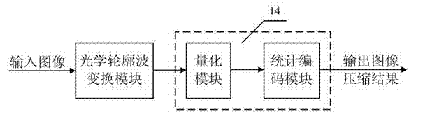
Image

Examples
Embodiment 1
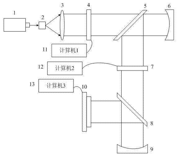
[0032] Example 1: In the optical profile wave conversion module, the HeNe laser 1 is located 22cm in front of the pinhole filter 2, and the pinhole filter 2 is located at the front focal plane of the collimating lens 3, which is installed 32cm behind the collimating lens 3 The first electrical addressing spatial light modulator 4 , A first beam splitter 5 is installed 22 cm behind the first electrically addressable spatial light modulator 4, a first Fourier mirror 6 is installed behind the first beam splitter 5, and the first electrically addressable spatial light modulator The distance between the device 4 and the first Fourier mirror 6 is equal to the focal length of the first Fourier mirror 6, and a second electrical addressing spatial light modulator 7 is installed under the first beam splitter 5, so The sum of the distance between the first Fourier mirror 6 and the first beam splitter 5 and the distance between the first beam splitter 5 and the second electrical addressing ...
Embodiment 2
[0039] Embodiment 2 has the same structure and method as embodiment 1, except that in embodiment 2, the helium-neon laser 1 is located 24cm in front of the pinhole filter 2, and the first electrical addressing spatial light modulation is installed 34cm behind the collimator lens 3. Device 4 , A first beam splitter 5 is installed 24 cm behind the first electrically addressable spatial light modulator 4, and a second beam splitter 8 is installed 24 cm below the second electrically addressable spatial light modulator 7.
Embodiment 3
[0040] Embodiment 3 has the same structure and method as embodiment 1, except that in embodiment 3, the helium-neon laser 1 is located 20cm in front of the pinhole filter 2, and the first electrical addressing spatial light modulation is installed 30cm behind the collimator lens 3. Device 4 , A first beam splitter 5 is installed 20 cm behind the first electrically addressable spatial light modulator 4, and a second beam splitter 8 is installed 20 cm below the second electrically addressable spatial light modulator 7.
[0041] Apply the optical contourlet transform module to realize the contourlet transform of the input image, such as figure 2 As shown, the helium-neon laser 1 forms parallel light through the pinhole filter 2 and the collimator lens 3 to irradiate the first electrical addressing spatial light modulator 4, and the first computer 11 controls the input image to be loaded into the first telescope. On the address spatial light modulator 4, the Fourier transform of the ...
PUM
 Abstract
Description
Claims
Application Information