Method and mould for manufacturing floor spring rotating shaft head

A production method and technology for floor springs, which are applied to metal extrusion dies and other directions, can solve the problems of weak product market competitiveness, slow processing speed and high processing costs, and achieve the effects of high appearance, high qualification rate and convenient use.

Active Publication Date: 2011-10-26
玉环市江洲机械有限公司
View PDF6 Cites 4 Cited by
  • Summary
  • Abstract
  • Description
  • Claims
  • Application Information

AI Technical Summary

Problems solved by technology

A comprehensive analysis of the above production methods shows that for the processing of this product, the use of friction press forging has the problem of high processing costs
The milling process has the defects of slow processing speed and low precision. If the surface roughness and precision need to be improved, multiple milling or polishing treatments are required.
Therefore, there are problems such as low production efficiency, high cost, and weak product market competitiveness.

Method used


Image

  • Method and mould for manufacturing floor spring rotating shaft head
  • Method and mould for manufacturing floor spring rotating shaft head
  • Method and mould for manufacturing floor spring rotating shaft head

Examples


Embodiment Construction

[0038] The following are specific embodiments of the present invention and in conjunction with the accompanying drawings, the technical solutions of the present invention are further described, but the present invention is not limited to these embodiments.

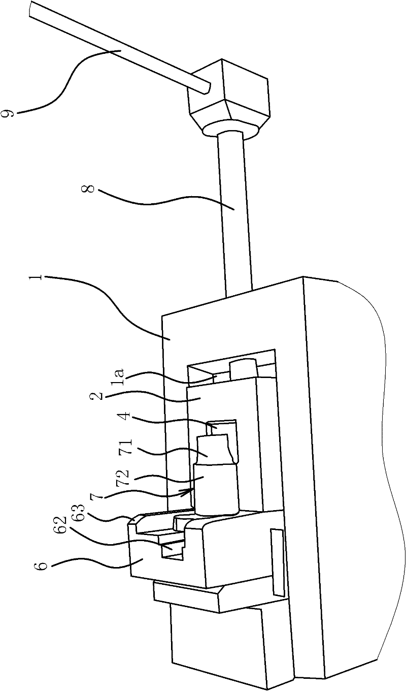
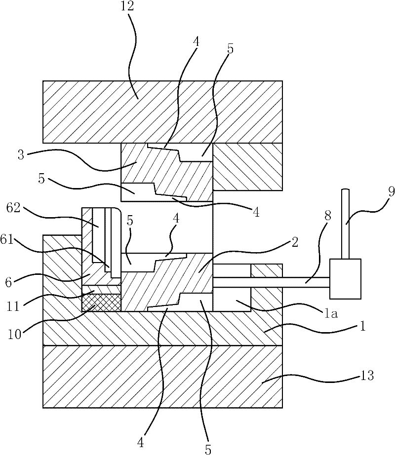
[0039] Such as figure 1 and figure 2 As shown, the mold for forming the head of the local spring shaft includes a lower mold 2, an upper mold 3 and a base 1 with a positioning groove 1a.

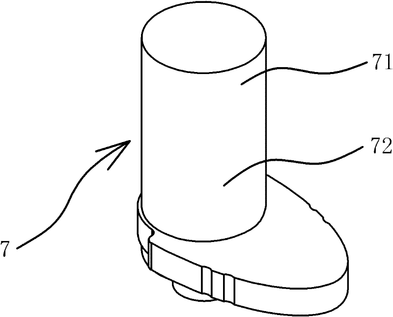
[0040] Specifically, the positioning groove 1a is in the shape of a cuboid. Both the lower die 2 and the upper die 3 are in a block shape, and the width of the lower die 2 is opposite to the width of the positioning groove 1a. A mold cavity 4 is provided on one end surface of the lower mold 2 and one end surface of the upper mold 3 . The mold cavity 4 on the lower mold 2 is fastened with the mold cavity 4 on the upper mold 3 to form a molding cavity corresponding to the structure of the head 71 of the rotating shaft 7 . More specifi...


PUM


Abstract

The invention provides a method and a mould for manufacturing a floor spring rotating shaft head, belonging to the technical field of mechanical engineering. The method solves the problems such as low production efficiency, high cost, weak market competitive power of products and the like in the existing method for manufacturing a rotating shaft. The method for manufacturing the floor spring rotating shaft head includes the steps of blank tooling, cold extrusion, surface treatment, etc. A mould for forming the floor spring rotating shaft head comprises a lower die, an upper die, a pedestal, aradial positioning mechanism and an axial positioning mechanism. A mould for trimming concave shoulder bottom surfaces of the floor spring rotating shaft head comprises a positioning mould and a forming mould, wherein flattening surfaces capable of corresponding to the concave shoulder bottom surfaces in position and structure one by one are arranged on one end of the forming mould, and a placinghole through which a workpiece head can penetrate is also arranged on the forming mould. The floor spring rotating shaft produced by the manufacturing method has the advantages of being low in production cost, beautiful in appearance and strong in market competitive power. The mould for forming the floor spring rotating shaft head has the advantages of being reasonable in design and convenient inuse.

Description

technical field [0001] The invention belongs to the technical field of mechanical engineering, and relates to a floor spring, in particular to a method for manufacturing a rotating shaft head of the floor spring. The invention also relates to a molding die, in particular to a molding die for the head of the floor spring shaft and a flattening die for the bottom surface of the concave shoulder of the head of the floor spring shaft. Background technique [0002] The floor spring is also a hydraulic door closer, which can be applied to almost all wooden, steel, aluminum alloy doors and frameless glass doors using glass door clips. [0003] There are many types of floor springs in the market, and Chinese patent literature once announced a floor spring sealing structure [Chinese Patent No.: ZL200620116212.7; Authorized Notice No.: CN2900733Y]. Local springs include key components such as camshafts, upper covers, bases and bearings. All floor springs have a rotating shaft whose ...

Claims


Application Information

Patent Timeline
Patent Type & Authority Applications(China)
IPC IPC(8): B23P15/00B21C25/02
Inventor 翁振栋
Owner 玉环市江洲机械有限公司
Why Eureka
Try Eureka