Two-stage rotary mechanism for small electric manipulator

An electric manipulator and rotary mechanism technology, applied in manipulators, manufacturing tools, joints, etc., can solve problems such as unfavorable miniaturization and complex structure, and achieve the effect of being conducive to miniaturization, compact structure and convenient control

Inactive Publication Date: 2011-10-26
HARBIN ENG UNIV
View PDF5 Cites 6 Cited by
  • Summary
  • Abstract
  • Description
  • Claims
  • Application Information

AI Technical Summary

Problems solved by technology

However, due to the limitations of volume, weight, energy and other conditions, there are few working manipulators suitable for unmanned unmanned underwater robots. The existing underwater electric manipulators have complex joint structures, which are not conducive to overall miniaturization. For example, the patent application number is 200610046218.6, titled "A Rotary Joint Structure of Underwater Electric Manipulator", and the technical solutions disclosed in related patent documents with patent application number 200810229973.7, titled "A Joint Mechanism of Underwater Electric Manipulator", etc.
In particular, there is no related patent in China on the structure of the wrist joint rotary motion that increases the degree of freedom of the underwater manipulator.

Method used


Image

  • Two-stage rotary mechanism for small electric manipulator
  • Two-stage rotary mechanism for small electric manipulator
  • Two-stage rotary mechanism for small electric manipulator

Examples


Embodiment Construction

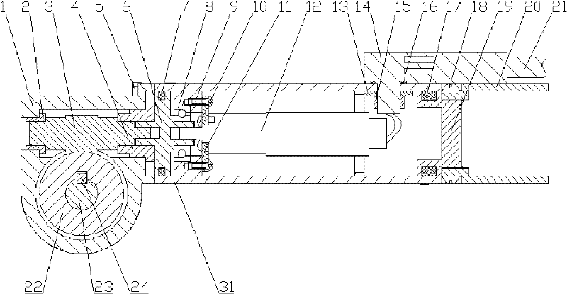
[0022] The present invention will be described in more detail below with reference to the accompanying drawings.

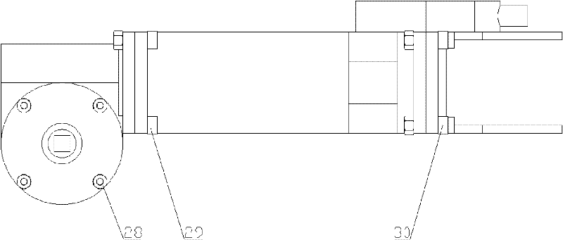
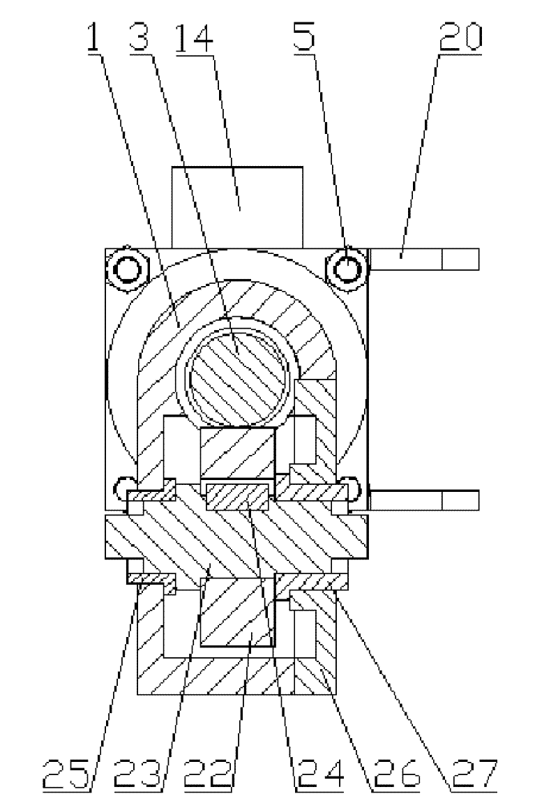
[0023] combine figure 1 , figure 2 , the main components of the present invention include the manipulator shell 15, the wrist joint drive motor 22, the claw drive motor 16, the wrist joint shell 6, the watertight cable socket 25, the manipulator shell cover 29, and the first stage rotary mechanism and the second stage The main structural components such as the slewing mechanism, the first-stage slewing mechanism includes the claw motor housing 14, the first-stage sliding bearing 13 and the first-stage gray ring 9, the second-stage slewing mechanism includes the claw drive shaft 1, the second-stage sliding Bearing 4 and second stage gray circle 5.

[0024] Wherein the wrist joint drive motor 22 is fixed with the wrist joint motor connection plate 20 through the wrist joint motor screw 21, the wrist joint motor connection plate 20 is fixed with the mechanical arm...


PUM


Abstract

The invention provides a two-stage rotary mechanism for a small electric manipulator, which comprises a manipulator, a wrist joint, a wrist joint driving motor, a paw driving motor, a first-stage rotary mechanism, a second-stage rotary mechanism, a paw support, a watertight socket and a watertight cable, wherein the watertight socket is installed at the rear part of the manipulator, the wrist joint driving motor is installed inside the manipulator; the first-stage rotary mechanism is installed at the front part of the mechanical arm; the paw driving motor is installed inside the first-stage rotary mechanism and a control cable of the paw driving motor passes through holes in the manipulator and the first-stage rotary mechanism; the wrist joint is connected with the first-stage rotary mechanism; the second-stage rotary mechanism is installed inside the wrist joint; and the paw support is installed at the end part of the wrist joint. In the two-stage rotary mechanism of the invention, wrist joint motion and paw motion are combined and two driving motors are packaged inside the manipulator in series, thereby reducing joint dimension, and the working depth of the manipulator is improved by means of the combination of Grameen circle sealing and angular contact bearing.

Description

technical field [0001] The invention relates to an underwater operation manipulator, in particular to a secondary rotary mechanism of a small manipulator driven by a motor. Background technique [0002] Underwater robot is an important tool for modern marine environment monitoring and resource development. With the continuous improvement of its working scope and operating requirements, higher requirements are put forward for its operating tools. At present, unmanned unmanned underwater robots have become a research hotspot due to their large working range and good concealment. The improvement of their working tools and working capabilities will further improve their work efficiency and expand their application fields. However, due to the limitations of volume, weight, energy and other conditions, there are very few operating manipulators suitable for unmanned unmanned underwater robots, and the existing underwater electric manipulators have complex joint structures, which ar...

Claims


Application Information

Patent Timeline
Patent Type & Authority Applications(China)
IPC IPC(8): B25J17/00B25J13/00
Inventor 王玉甲张铭钧彭生全褚振忠赵文德徐建安殷宝吉
Owner HARBIN ENG UNIV
Why Eureka
Try Eureka