Novel grinding apparatus

A grinding device and a new type of technology, applied in beverage preparation devices, kitchen utensils, household utensils, etc., can solve the problems of slow discharge, too large, and inability to discharge completely, and achieve the effect of preventing insufficient grinding

Active Publication Date: 2011-11-02
MIDEA GRP CO LTD
View PDF3 Cites 0 Cited by
  • Summary
  • Abstract
  • Description
  • Claims
  • Application Information

AI Technical Summary

Problems solved by technology

However, there are two problems in this structure. One is that the distance between the movable grinding wheel and the static grinding wheel is fixed. When encountering larger particles of material, it is easy to get stuck, and as the grinding progresses, the material becomes smaller. At this time, the moving grinding wheel and the static grinding wheel The gap of the static grinding wheel is too large to fully grind; the second is that the power of the slurry discharged from the grinding mechanism is insufficient, and the slurry is discharged only by the centrifugal force generated by the rotation of the moving grinding wheel, and the discharge speed is slow, and it is easy to cause part of the slurry to remain at the bottom of the inner grinding wheel , cannot be completely discharged, resulting in part of the material remaining at the bottom of the grinding mechanism, insufficient grinding
In summary, the existing technology results in that the material is not ground fine enough, the material is not smooth enough, and the material is easy to get stuck

Method used


Image

  • Novel grinding apparatus
  • Novel grinding apparatus
  • Novel grinding apparatus

Examples


Embodiment 1

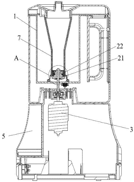
[0029] Such as figure 1 As shown, it is a schematic structural diagram of the grinding device of the present invention, including a container 1 and a base 5, a movable grinding wheel 21 and a static grinding wheel 22 that can rotate relatively at the bottom of the container 1, and a motor 3 is housed in the base 5. The moving grinding wheel 21 is connected to the motor 3 through a drive shaft 4 passing through its center, a rotation gap is provided between the moving grinding wheel 21 and the static grinding wheel 22, and the opposite faces of the moving grinding wheel 21 and the static grinding wheel 22 are provided with matching cutting edges.

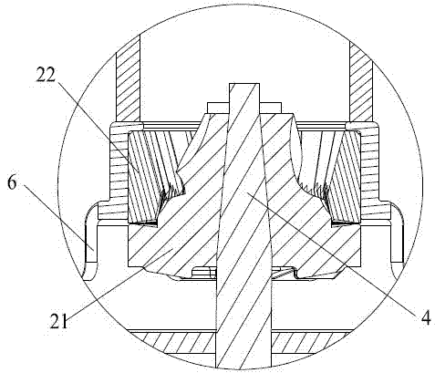
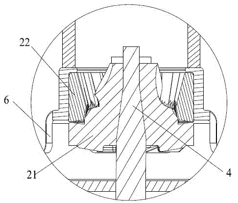
[0030] The moving grinding wheel 21 and the driving shaft 4 are in a sliding connection, and the connection between the driving shaft 4 and the moving grinding wheel 21 is a matching structure of a tapered column and a tapered hole, that is, the driving shaft 4 is in a conical structure as a whole at the connection, and the specific s...

Embodiment 2

[0035] This embodiment is similar in structure to Embodiment 1, as Figure 7 and Figure 8 As shown, the difference is only that the movable grinding wheel 21 and the static grinding wheel 22 are matched up and down, the movable grinding wheel 21 and the static grinding wheel 22 are disc-shaped, the movable grinding wheel 21 is placed under the static grinding wheel 22, and the middle part of the static grinding wheel 22 is provided with a feeding port. 21 and static grinding 22 gap openings on the outside of the wheel are discharge openings. The rotation gap between the movable grinding wheel 21 and the static grinding wheel 22 gradually becomes smaller from the feed inlet to the discharge outlet.


PUM


Abstract

The invention relates to the technical field of soybean milk makers and specifically relates to a novel grinding apparatus, comprising a motor, a movable grinding wheel and a static grinding wheel, wherein the movable grinding wheel and the static grinding wheel can rotate relatively. The movable grinding wheel is connected to the motor through a drive shaft at the center of the movable grinding wheel, a rotation gap is formed between the movable grinding wheel and the static grinding wheel, and the movable grinding wheel is connected to the drive shaft in a sliding way. At least a lower partof a connection place between the drive shaft and the movable grinding wheel is a conical post and conical hole matching structure widening from top to bottom gradually. According to the invention, by means of the special design of the conical drive shaft, the material can be prevented from getting stuck and ensured to be ground adequately.

Description

technical field [0001] The invention relates to the field of food grinding, in particular to a novel grinding device for beans. Background technique [0002] With the development of food machinery, grinding soybean milk machine came into being. Compared with the blade type soybean milk machine, the grinding stone soybean milk machine has the advantages of high crushing degree and low noise. [0003] In the existing grinding type soybean milk machine, the material is added through the hopper, and then the movable grinding wheel and the static grinding wheel that can rotate relatively are used to achieve grinding, and then the slurry is discharged to the cup body from the gap between the inner and static grinding wheels. However, there are two problems in this structure. One is that the distance between the movable grinding wheel and the static grinding wheel is fixed. When encountering larger particles of material, it is easy to get stuck, and as the grinding progresses, the...

Claims


Application Information

Patent Timeline
Patent Type & Authority Applications(China)
IPC IPC(8): A47J31/42A23C11/10
Inventor 李前荣焦启华
Owner MIDEA GRP CO LTD
Why Eureka
Try Eureka