Automatic operation device of upper drill floor and lower drill floor of drill rod

A technology for operating devices and drill pipes, which is applied to drill pipes, drill pipes, drilling equipment, etc. It can solve the problems of high requirements for operators, complicated operation process, and low production efficiency, and achieve low mechanization and automation and simple operation Reliable and reasonable structural design effect

Inactive Publication Date: 2011-11-02
SHENGLI OIL FIELD HAISHENG ENVIRONMENTAL PROTECTION ENG
5 Cites 24 Cited by

AI-Extracted Technical Summary

Problems solved by technology

This kind of operation requires that the upper and lower two operators of the pneumatic winch must cooperate well and synchronize as much as possible. The requirements for the operators...

Method used

7, circuit signal line adopts aviation circuit plug at catwa...

Abstract

The invention relates to the mechanical field of the well drilling engineering, and in particular relates to an automatic operation device of the upper drill floor and the lower drill floor of a drill rod. The technical scheme is as follows: the automatic operation device of the upper drill floor and the lower drill floor of a drill rod comprises a ramp, a catwalk, a catwalk support frame and a catwalk car in sliding fit with the catwalk, wherein the ramp is provided with the ramp car in sliding fit with the ramp; the butt joint position of the lower end of the ramp and the catwalk is respectively provided with a ramp pushing and blocking mechanism and a turnover mechanism; the catwalk close to the turnover mechanism is provided with a lifting mechanism; the middle of the catwalk is provided with at least two drill rod pushing and disassembling mechanisms at intervals; and all operation mechanisms in the device can be connected to the controller in a wired or wireless mode. The automatic operation device has the characteristic of reasonable structural design, is convenient and reliable to control, saves manpower and is efficient and safe.

Application Domain

Technology Topic

Butt jointDrill floor +3

Image

  • Automatic operation device of upper drill floor and lower drill floor of drill rod
  • Automatic operation device of upper drill floor and lower drill floor of drill rod
  • Automatic operation device of upper drill floor and lower drill floor of drill rod

Examples

  • Experimental program(1)

Example Embodiment

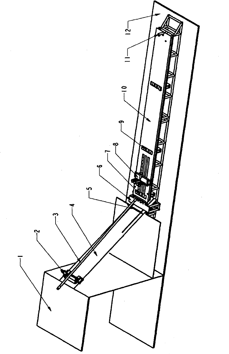
[0013] Reference figure 1 The automatic device for drilling up and down the drill floor of this embodiment includes: the ramp 4 is lapped on the drilling platform 1 obliquely upward, and the lower part is fixed on the support frame on the ground 12 together with the catwalk 10. The ramp 4 is provided with a ramp car 2 which is in sliding cooperation with the ramp, and a ramp push block mechanism 5 is provided at the lower end of the ramp. A turning mechanism 6 is provided at the front end of the catwalk 10 (that is, the docking part with the ramp). On the catwalk backward along the turning mechanism 6 are a lifting mechanism 7, a catwalk vehicle 8, two sets of spaced apart drill rod pushing and unloading mechanisms 9 and Catwalk car anti-drop block 11. The drill rod 3 is located on the turning mechanism 6 and the ramp car 2.
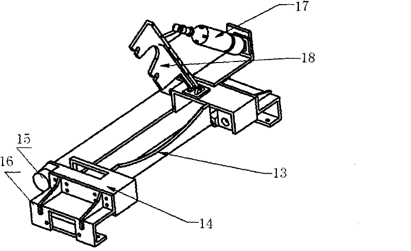
[0014] Reference attached figure 2 , The main body 14 of the ramp car 2 is connected to the lower drill rod holder 13 in the middle, one end of the drill rod upper holder 18 is hinged, and the ramp car driving cylinder 17 is connected at its hinge end to drive the drill rod upper holder 18 and the drill rod lower The clamping base 13 performs opening and closing coordination for clamping and releasing the drill rod. The two ends of the main body 14 of the ramp car are respectively provided with a wheel roller 15 and a limiting block 16 which are connected with the ramps 23 on both sides of the ramp 4 (see image 3 ) Sliding and limit coordination.
[0015] Reference attached image 3 , The ramp pushing mechanism 5 is axially connected with a V-shaped baffle 20 on the inner side of the lower end of the ramp 4, and the baffle 20 is driven and rotated by a baffle driving cylinder 19 connected to the ramp. Its function is to block the lower end of the drill rod on the baffle during the process of lowering the drill rod.
[0016] Reference attached Figure 4 , The turning mechanism 6 is that the turning plate 25 is axially connected to the front end of the catwalk, and the turning plate 25 is connected to the turning plate driving cylinder 24 under the turning plate 25, so that the turning plate is turned back and forth along its axis 26. The connecting shaft 26 of the flap is provided with three V-shaped claws 27 that cooperate with the groove on the top plate of the drill rod of the lifting mechanism 7. Its function is that the end of the drill rod is on the flip plate, and the end of the flip flip plate is lifted up and under the limit of the V-shaped claw, it is smoothly sent into the support plate of the catwalk cart and the drill rod holder.
[0017] Reference attached Figure 5 , The two ends of the car body 29 of the catwalk 8 are respectively provided with rollers 32 and side seats 31. The rollers 32 and the side seats 31 are connected to the slideways 28 on both sides of the catwalk (see Figure 4 ) To form a sliding fit, the front side of the car body is provided with a support plate 34 that overlaps the drill rod. The upper shaft of the support plate 34 is connected to the drill rod holder 33. The shaft of the drill rod holder 33 is connected to the catwalk driving cylinder 30 and the drill rod The clamping seat 33 is provided with three grooves and forms a clamping fit with the drill rod 3. The catwalk vehicle 8 is reciprocated linearly by a motor provided at the lower part of the catwalk in cooperation with a pull rope or a chain. Its function is to push and drag the drill rod to move forward and back along the catwalk after locking the lower joint of the drill rod when the drill rod is up and down, so as to achieve the role of transporting the drill rod. In order to control the front and rear travel of the catwalk on the catwalk, the front and back travel stop switches of the catwalk are respectively arranged before and after the catwalk to ensure that the catwalk stops immediately after reaching the designated position.
[0018] Reference attached Image 6 The lifting mechanism 7 is connected by the top plate 35 of the drill rod and the top plate driving cylinder 36 located below the top plate of the drill rod to form the up and down reciprocating movement of the top plate of the drill rod. The end surface of the top plate of the drill rod is provided with three parallel grooves. Its function is to lift the front end of the drill rod during the process of lifting the drill rod, and then the catwalk vehicle will push it forward into the deck of the ramp vehicle. The drill rod pushing and unloading mechanism 9 is similar in structure to the lifting mechanism 7, except that there are two driving cylinders under the top plate of the drill rod. Its function is that when the drill rod is lowered, the top plate of the drill rod is tilted and turned by the driving cylinder on one side, and the drill rod rolls to the drill rod frame on one side; when the drill rod is up, the driving cylinder makes the top plate of the drill rod lower to the drill rod Below the frame, put the drill rod on the drill rod frame into the top plate of the drill rod and lift it to the catwalk, and the catwalk cart will push forward.
[0019] In this embodiment, the ramp pushing mechanism, turning mechanism, lifting mechanism, pushing and unloading mechanism and catwalk drill rod holder can all be driven by hydraulic or pneumatic pressure, and the driving cylinder matched with it can be hydraulic or pneumatic driving cylinder. Pneumatic drive mode is preferred in this device. All operating mechanisms of the device are connected to the controller in a wired or wireless manner, which is convenient to further improve the degree of automation of the device, and can automatically control the entire control.
[0020] The working process of the device will be further described below in order to better understand the present invention.
[0021] The automatic operation device for drill rod up and down drill floor mainly has two functions: upper drill rod and lower drill rod. The lower drill rod can be operated with three drill rods at the same time, and the upper drill rod requires a single operation. Now take one drill rod as an example. The breakdown is as follows:
[0022] Drilling process:
[0023] 1. Use the drill floor pneumatic drawworks to slide a single drill rod from top to bottom along the groove on the drill rod ramp to the turning mechanism (a group of three each).
[0024] 2. Start the catwalk vehicle to move forward, the catwalk vehicle runs forward along the catwalk, and stops when approaching the forward end position, so that the catwalk vehicle stops at a predetermined position (the position is equipped with a stop travel switch, if you press the stop button, In time, the catwalk will automatically stop under the control of the travel switch).
[0025] 3. Start the catwalk car drill rod holder cylinder, the drill rod holder is opened, and the front travel switch is activated at the same time, the locking block rises to block the catwalk car, and the circuit self-protection stops at the upper position.
[0026] 4. Start the drill rod turning mechanism, the drill rod is turned from the turning plate of the turning mechanism to the front support plate of the catwalk, and then the turning mechanism is reset and stays in the reset position.
[0027] 5. Start the catwalk car drill rod holder cylinder, extend the holder to tightly press the three drill rods. When the catwalk vehicle runs backwards, as the drill rod slides down the ramp, the inclination angle decreases, and the cylinder rod continues to extend, always compressing the drill rod.
[0028] 6. Start the front travel switch of the catwalk, the lock stop of the catwalk will drop and keep it in a low position.
[0029] 7. Start the catwalk to move backward, and the catwalk starts to move backwards driven by the electric motor and the transmission system. When the catwalk vehicle runs to the predetermined drill pipe discharge position, because there is a travel position switch at this position, the catwalk vehicle stops by itself, and the travel switch is activated after the catwalk vehicle, and the drill pipe holder rises and remains at a high position. .
[0030] 8. The catwalk continues to move backward, and the catwalk starts to move backwards under the drive of the motor and transmission system.
[0031] Under the action of the inertial force of the drill rod, the drill rod will fall on the drill rod pushing and unloading mechanism of the catwalk. The catwalk vehicle continues to run backwards until it runs to a proper position of the drill pipe and stops.
[0032] 9. Start the left (right) side-turning cylinder of the top plate of the drill rod, and the 3 drill rods will roll towards the drill rod holder on the left (right) side of the catwalk under the action of the drill rod pushing and unloading mechanism.
[0033] 10. After the drill rod rolls down from the catwalk, the left (right) side of the drill rod top plate rolls over the cylinder to restore its original shape.
[0034] 11. Start the catwalk vehicle to move forward again, the catwalk vehicle will move forward and start the next working cycle.
[0035] Drilling process:
[0036] Contrary to the method of drilling down. The operation point is different from the lower drill pipe: first, the drill pipe pushing mechanism is lowered to the low point, the drill rod enters the drill pipe top plate of the pushing mechanism, the pushing mechanism is started to rise, the catwalk car goes forward into the lower end of the drill rod, and then the drill rod is lifted and unloaded When the mechanism falls, the drill rod falls into the front support plate of the catwalk cart and is clamped by the clamp.
[0037] After the drill rod is pushed forward by the catwalk to the lifting mechanism, the lifting mechanism lifts the front end of the drill rod away from the catwalk surface, and the catwalk continues to push the drill rod forward to make the drill rod enter the slope at a certain angle In the deck of the road cat road car.
[0038] Features of the embodiment device of the present invention
[0039] 1. High production efficiency, low labor intensity, safe and simple operation.
[0040] 2. The working principle is advanced and simple, all mechanized operation.
[0041] 3. Easy to move and install, and the occupied space is basically the same as the catwalk currently used by the well team.
[0042] 4. The air source adopts the air source of the drilling rig air circuit system, and no additional configuration is required.
[0043] 5. Except for the 380V 3-phase power supply used in the main circuit of the motor, the other control circuits all use low voltage (24V AC). The main circuit is equipped with a leakage protection switch, which greatly guarantees the safety of electric power for operators.
[0044] 6. The gas pipeline mainly uses PU pipes, and the catwalk (front and rear brackets) disconnects and the air source main interface adopt self-sealing quick-plug connectors to prevent dust from entering the gas system. The connection is convenient. The PU pipes are very easy to replace after aging. Convenience.
[0045] 7. The circuit signal line adopts the aviation circuit plug at the disconnection of the catwalk (front and rear supports), which is easy to disassemble and assemble.
[0046] 8. The drill pipe turning cylinder is a jog work mode, and the cylinder is reset immediately when it is not pressed; the cylinder is a self-holding work mode, which can be stopped at the high and low working positions respectively. When there is no signal, they are all in the low waiting position for work After the signal rises and protects itself, when the working signal is interrupted, it quickly returns to the waiting position.
[0047] 9. Flip the left or right side of the drill pipe and set the direction selection switch to prevent misoperation in unexpected directions.
[0048] 10. When the catwalk car is running, the circuit is interlocked, and each cylinder will not move.

PUM

no PUM

Description & Claims & Application Information

We can also present the details of the Description, Claims and Application information to help users get a comprehensive understanding of the technical details of the patent, such as background art, summary of invention, brief description of drawings, description of embodiments, and other original content. On the other hand, users can also determine the specific scope of protection of the technology through the list of claims; as well as understand the changes in the life cycle of the technology with the presentation of the patent timeline. Login to view more.

Similar technology patents

Physical simulation experiment method and device for monitoring shearing force of earthquake triggering cross section surface

ActiveCN101609157AReal-time warning and forecastReasonable structural designForce measurementSeismologySeismic hazardMechanical models
Owner:CHINA UNIV OF MINING & TECH (BEIJING)

Classification and recommendation of technical efficacy words

  • Reasonable structural design
  • Easy and reliable operation

DC motor with externally mounted carbon brush

InactiveUS20060028091A1Simply constructedEasy and reliable operationRotary current collectorSupports/enclosures/casingsMagnetElectrical connection
Owner:XU XIAOHUA

Fiber array coupling output device, system and method for single photon source device

ActiveCN106199856AIncrease the exit rateEasy and reliable operationCoupling light guidesPhysicsFiber array
Owner:INST OF SEMICONDUCTORS - CHINESE ACAD OF SCI

Injector clamping device for injection pump

ActiveCN106362237AEasy and reliable operationPressure infusionPotentiometerInjector
Owner:苏州麦德迅医疗科技有限公司
Why Eureka
Try Eureka