
Cyclone drying and solvent recycling system

A recycling system and swirling technology, applied in the direction of drying solid materials, drying gas arrangement, drying, etc., can solve the problems of direct drying of unsuitable filter cake-like or agglomerated materials, improve drying efficiency, reduce dust removal pressure, The effect of not easy to scale

Active Publication Date: 2011-11-02
JIANGSU XIANFENG DRYING ENG
View PDF10 Cites 8 Cited by
  • Summary
  • Abstract
  • Description
  • Claims
  • Application Information

AI Technical Summary

Problems solved by technology

Fluidized drying is generally not suitable for direct drying of filter cake or agglomerated materials, and the condensation effect of the above-mentioned closed-circuit fluidized drying device needs to be further improved

Method used


Image

  • Cyclone drying and solvent recycling system
  • Cyclone drying and solvent recycling system
  • Cyclone drying and solvent recycling system

Examples


Embodiment 1

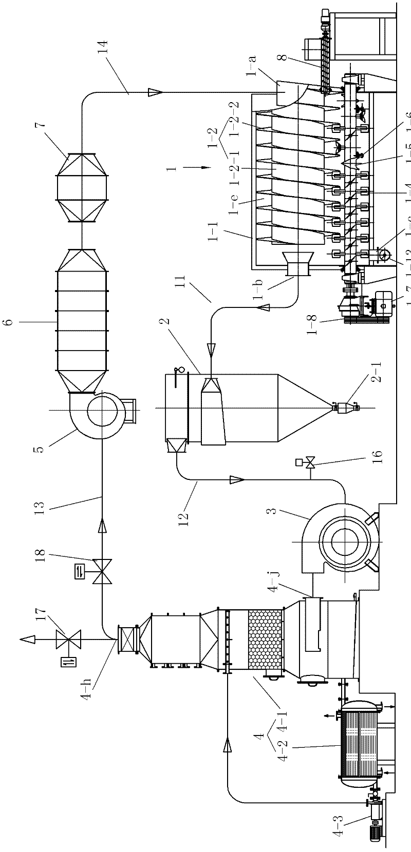
[0021] See Figure 1 to Figure 11 , This embodiment has a drying host 1, a bag dust removal device 2, an induced draft fan 3, a composite condensing device 4, a blower 5, a heater 6, and a filter 7.

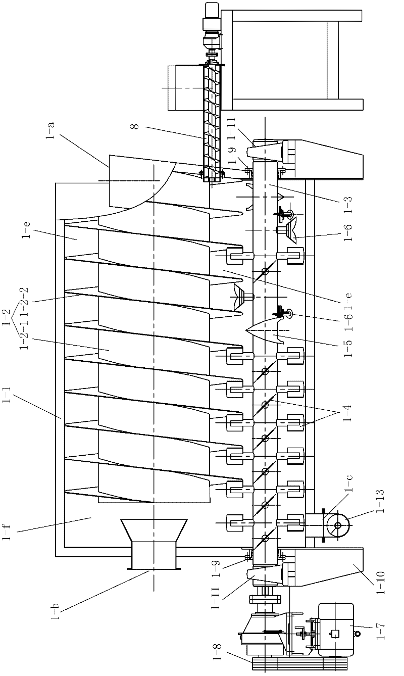
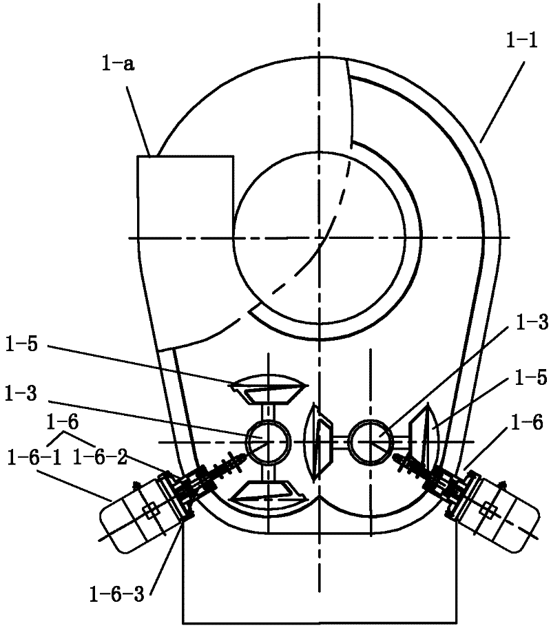
[0022] The main drying machine 1 has a body 1-1 supported by a frame 1-10, the upper part of the main drying machine 1 is arc-shaped, and the bottom is W-shaped. The upper part of the body cavity is provided with an airflow guide 1-2, and the space behind the body cavity behind the airflow guide 1-2 is a swirl chamber 1-f. The airflow guide 1-2 includes a core tube 1-2-1 and a spiral band 1-2-2 fixed on the core tube 1-2-1, and the spiral groove becomes a spiral airflow channel 1-e, and the spiral airflow channel The rear end of 1-e communicates with the settling chamber 1-f, and the airflow guide 1-2 is fixed by fixing the upper half edge of the spiral belt 1-2-2 on the inner wall of the body cavity.

[0023] The lower part of the body cavity is provided with a pair of stirrin...

Embodiment 2

[0029] The difference between embodiment 2 and embodiment 1 is that the compound condensation device 4 taken is different, see Figure 12 , compound condensing device 4 with inner finned tube condenser 4-4, gas-liquid separator 4-5 and liquid collection tank 4-6, liquid collection tank 4-6 is equipped with tube and tube cooler 4-7 . The above-mentioned inner finned tube condenser 4-4 and the gas-liquid separator 4-5 are connected to the liquid collecting tank 4-6 and communicate with the liquid collecting tank 4-6, and the hot air inlet 4-j of the composite condensing device 4 It is arranged on the top of the condenser 4-4, and the cold air outlet 4-h of the composite condensing device 4 is arranged on the top of the gas-liquid separator 4-5. The liquid collecting tank 4-6 is provided with a rectifying tower.


PUM


Abstract

The invention discloses a cyclone drying and solvent recycling system, which is provided with a drying host machine, a bag-type dust removing device, a draught fan, a composite condensing device, a blower, a heater and a filter, wherein the upper part of the machine body cavity of the drying host machine is provided with an air current guide piece; the air current guide piece comprises a core pipe and a spiral band fixed on the core pipe; a spiral groove serves as a spiral air current channel; the back end of the spiral air current channel is communicated with a sedimentation chamber; the edge of the upper half part of the spiral band is fixed on the inner wall of the machine body cavity; the lower part of the machine body cavity is provided with a pair of stirring shafts; and each stirring shaft is provided with multiple pairs of paddle shoveling plates and coulters. By adopting the cyclone drying and solvent recycling system, the application range of fluidization drying is expanded, paste, slurry, particle, powder and filter cake materials can be dried, and crushing and drying are completed in one dryer. The volume drying intensity of the cyclone drying and solvent recycling system is far higher than that of ordinary fluidization drying equipment, the final water content can be lowered to an extremely low value in one drying host machine, and the defect of strict requirement for air current material drying on the initial water content of a material is overcome.

Description

technical field [0001] The invention relates to a cyclone drying and solvent recovery system. Background technique [0002] Chinese Patent No. 200820037835.4 utility model patent specification discloses a dual-shaft sealed hollow paddle dryer, which includes a shell with a jacket, the section of the shell is W-shaped, and the two ends of the shell are equipped with There is an upper cover on the top of the shell jacket, and there are two hollow stirring shafts between the end covers. The two hollow stirring shafts are respectively located in the two grooves of the W shape. The hollow stirring shafts are equipped with hollow paddles. The two hollow stirring shafts are connected by gears; the hollow stirring shaft is provided with a hollow blade, the top of the upper cover is provided with a steam outlet, the left end of the upper cover is provided with a material inlet, and the right end of the shell jacket is provided with a discharge There is a rotary joint at the end of t...

Claims


Application Information

Patent Timeline
Patent Type & Authority Applications(China)
IPC IPC(8): F26B21/02F26B21/14F26B25/00
Inventor 谢洪清查协芳
Owner JIANGSU XIANFENG DRYING ENG
Learn More