Explosive collision sensitivity instrument

A technology of sensitivity meter and explosives, which is applied in the field of explosives performance testing devices, can solve the problems of poor test consistency, difficult to guarantee test conditions, and low test accuracy, so as to ensure consistency, improve test accuracy and reliability, and high test accuracy Effect

Inactive Publication Date: 2011-11-02
ZHONGBEI UNIV
View PDF2 Cites 17 Cited by
  • Summary
  • Abstract
  • Description
  • Claims
  • Application Information

AI Technical Summary

Problems solved by technology

[0009] In order to solve the problems of poor test consistency, low test accuracy and difficult to guarantee test conditions of the existing impact sensitivity test device, the present invention provides an explosive impact sensitivity instrument

Method used


Image

  • Explosive collision sensitivity instrument
  • Explosive collision sensitivity instrument
  • Explosive collision sensitivity instrument

Examples


Embodiment 1

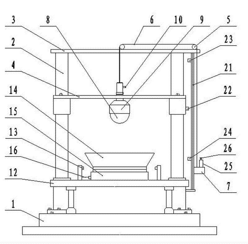
[0023]Explosive impact sensitivity instrument, including drop weight lifting and positioning mechanism, drop weight fixing and releasing mechanism, impact device mechanism, light control anti-secondary impact mechanism, and overall control mechanism;

[0024] The falling weight lifting and positioning mechanism includes a base 1, a lifting guide rail 2 vertically fixed on the upper surface of the base 1, an upper fixing plate 3 horizontally fixed on the top of the lifting guide rail 2, and a sliding connection between its end and the lifting guide rail 2. Lifting plate 4; a pulley block 5 is installed on the upper surface of the upper fixing plate 3, and a lifting rope 6 is wound on the pulley block 5; one end of the lifting rope 6 is connected with a reel 7, and the other end hangs down to fix the falling weight fixing and releasing mechanism;

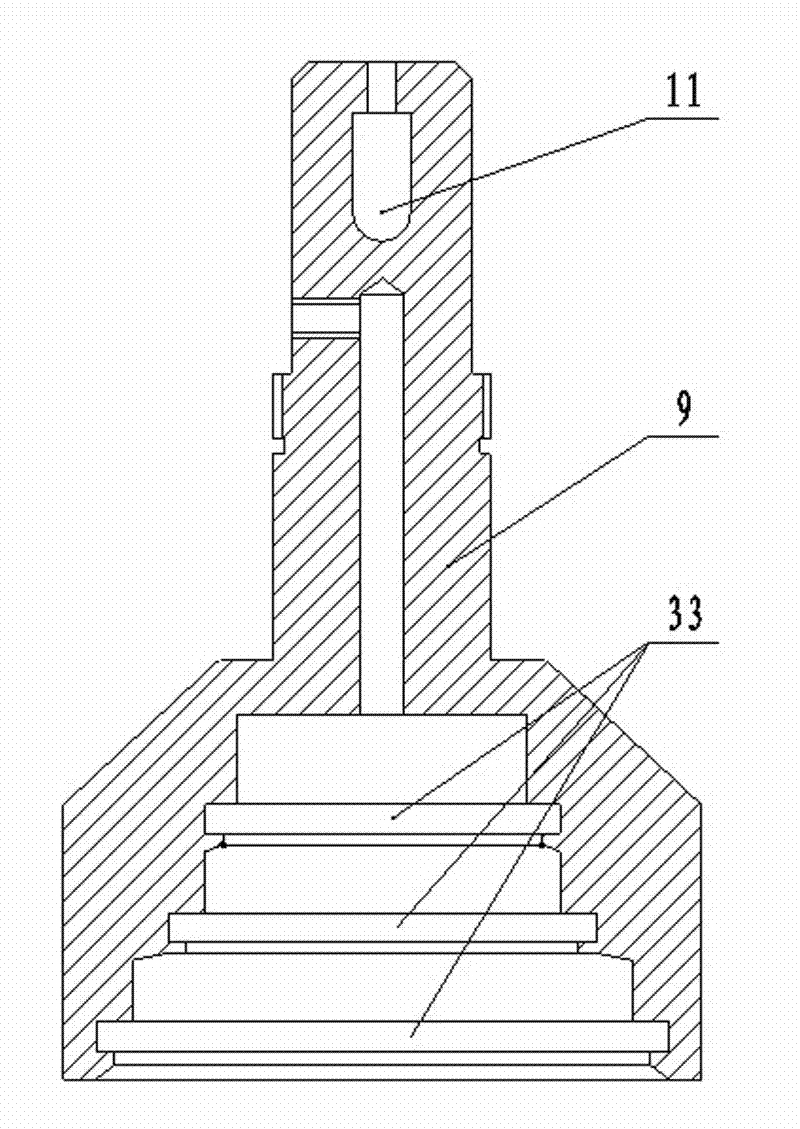
[0025] The falling weight fixing and releasing mechanism includes a dropping weight 8, a dropping weight suction cover 9, and a vacuu...

Embodiment 2

[0035] Explosive impact sensitivity instrument, including drop weight lifting and positioning mechanism, drop weight fixing and releasing mechanism, impact device mechanism, light control anti-secondary impact mechanism, and overall control mechanism;

[0036] The falling weight lifting and positioning mechanism includes a base 1, a lifting guide rail 2 vertically fixed on the upper surface of the base 1, an upper fixing plate 3 horizontally fixed on the top of the lifting guide rail 2, and a sliding connection between its end and the lifting guide rail 2. Lifting plate 4; a pulley block 5 is installed on the upper surface of the upper fixing plate 3, and a lifting rope 6 is wound on the pulley block 5; one end of the lifting rope 6 is connected with a reel 7, and the other end hangs down to fix the falling weight fixing and releasing mechanism;

[0037] The falling weight fixing and releasing mechanism includes a dropping weight 8, a dropping weight suction cover 9, and a vacu...


PUM


Abstract

The invention relates to an explosive performance detection device, in particular to an explosive collision sensitivity instrument, which is mainly used for solving the problems of poor testing consistence, low testing accuracy and difficulty in ensuring the testing conditions existing in the conventional collision sensitivity testing device. The explosive collision sensitivity instrument comprises a drop hammer elevating and positioning mechanism, a drop hammer fixing and releasing mechanism, a collision device mechanism, an optically-controlled anti-secondary-collision mechanism and an integral control mechanism, wherein the drop hammer elevating and positioning mechanism comprises a base, an elevating guide rail which is vertically fixed on the upper surface of the base, an upper fixed plate which is horizontally fixed at the top end of the elevating guide rail and an elevating plate of which the end part is connected with the elevating guide rail in a sliding manner; and the drop hammer fixing and releasing mechanism comprises a drop hammer, a drop hammer sucking cover and a vacuum pump connecting pipe. The explosive collision sensitivity instrument has the characteristics of Custer and 12-type tool testing structures, can be used for detecting the sensitivity properties such as collision explosion probability, characteristic drop height and the like of an explosive, and can be used for detecting the safety performance of the explosive.

Description

technical field [0001] The invention relates to an explosive performance detection device, in particular to an explosive impact sensitivity instrument. Background technique [0002] Impact sensitivity is one of the most important items for testing the safety of explosives, which refers to the degree of difficulty for explosives to explode under the action of mechanical impact. The safety of explosives in the process of production, transportation, storage and use can be directly and effectively measured through the measurement and research on the impact sensitivity of explosives. [0003] The impact sensitivity meter is developed to measure the impact sensitivity of explosives. Its basic working principle is: put the impact device with a certain amount of explosive samples into the special positioning device, and lift the weights of different masses to After a certain height, it is released by the release device, and the heavy hammer falls freely to hit the sample. After reb...

Claims


Application Information

Patent Timeline
Patent Type & Authority Applications(China)
IPC IPC(8): G01N19/00
Inventor 吕春玲张景林靳荣桃周得才
Owner ZHONGBEI UNIV
Why Eureka
Try Eureka