MIMO (Multiple Input Multiple Output) step-by-step parallel detection method

A detection method and a multi-output technology, applied in diversity/multi-antenna systems, space transmit diversity, shaping networks in transmitters/receivers, etc., can solve matrix pseudo-inverse calculations with high complexity, increased complexity, and continuous sorting Interference eliminates some problems such as error propagation in OSIC, and achieves the effect of improving detection performance, reducing complexity, and suppressing error propagation

Inactive Publication Date: 2013-08-14
XIDIAN UNIV
View PDF6 Cites 0 Cited by
  • Summary
  • Abstract
  • Description
  • Claims
  • Application Information

AI Technical Summary

Problems solved by technology

In 2002, E.G.Larsson et al published "On Maximum-Likelihood Detection and Decoding for Space-Time Coding Systems" in "IEEE Trans. "Maximum Likelihood Detection and Decoding in Space-Time Coding Systems" proposed a maximum likelihood ML detection method, which can obtain the best error probability performance, but the complexity increases exponentially with the number of transmitting antennas; 2004 "Combined maximum likelihood and ordered successive interference cancellation grouped detection algorithm for multistream MIMO" "Segmented Detection Method for Maximum Likelihood Decision Feedback Equalization in Multi-stream MIMO" proposes a segmented detection method of maximum likelihood decision feedback equalization ML-DFE, which improves the detection structure and maximizes The combination of likelihood ML and sorting continuous interference cancellation OSIC method seeks a compromise between complexity and performance, but the sorting continuous interference cancellation OSIC part still introduces error propagation, and the matrix pseudo-inverse operation and maximum likelihood ML part are complex high degree

Method used


Image

  • MIMO (Multiple Input Multiple Output) step-by-step parallel detection method
  • MIMO (Multiple Input Multiple Output) step-by-step parallel detection method
  • MIMO (Multiple Input Multiple Output) step-by-step parallel detection method

Examples


Embodiment Construction

[0018] The present invention will be further described below with reference to the accompanying drawings.

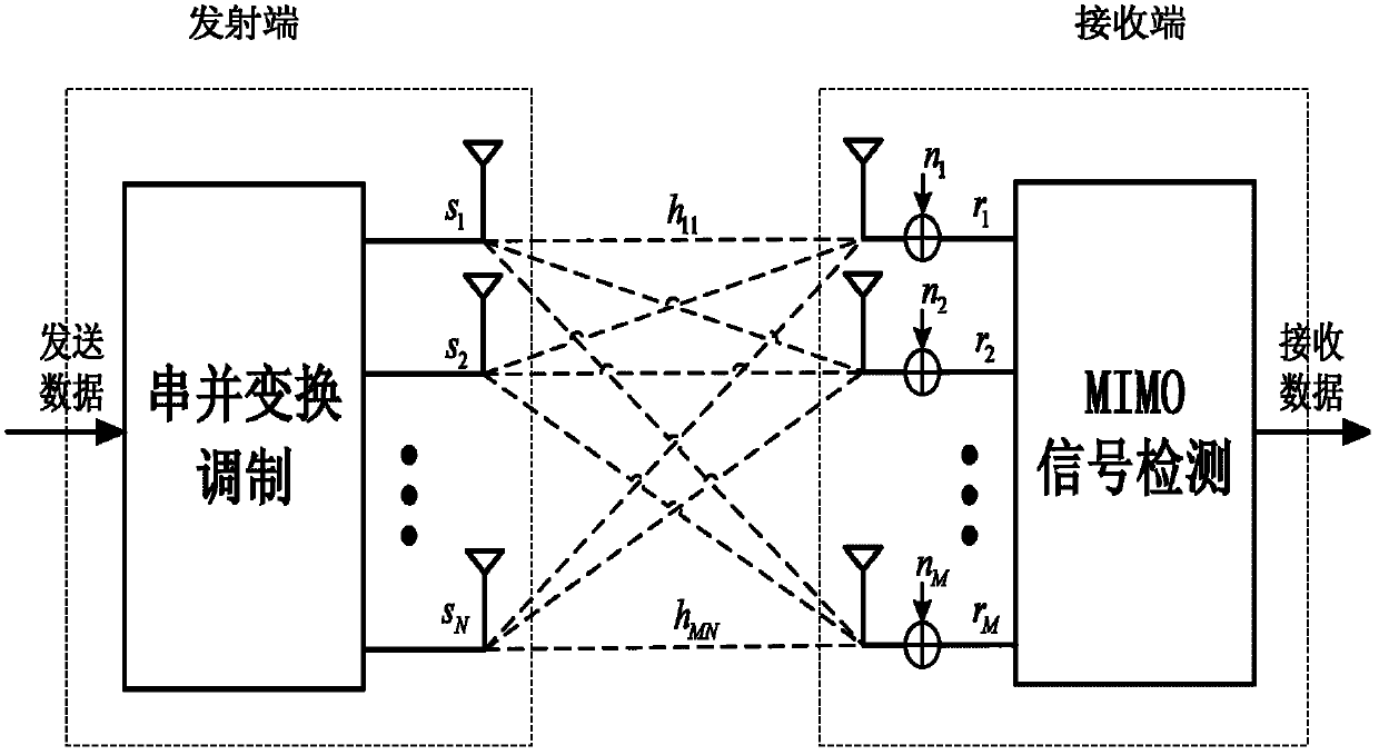
[0019] The multiple-input multiple-output MIMO system model used in the present invention is as follows: image 3 As shown, after the transmitted data is modulated by serial-to-parallel conversion, the transmitted signal at the transmitting end is obtained as s=[s 1 ,…,s N ] T , the transmitted signal reaches the receiving end after experiencing channel fading, and then superimposed on the noise signal n=[n 1 ,...,n M ] T , the corresponding received signal is r=[r 1 ,...,r M ] T , and then use the MIMO signal detection of the present invention to obtain the received data. where r i , i=1,..., M is the received signal of the receiving antenna i, s j , j=1,...,N is the transmit signal of transmit antenna j, that is, the jth substream of transmit signal s; n i , i=1, ..., M is the noise signal of the receiving antenna i, N is the number of transmitting antennas,...


PUM


Abstract

The invention discloses an MIMO (Multiple Input Multiple Output) step-by-step parallel detection method which is mainly used for solving the problems that the complexity and performance of the prior art are difficult to balance. The MIMO step-by-step parallel detection method disclosed by the invention comprises the following realization steps: (1) obtaining a substream detection sequence according to a channel transmission matrix, and then obtaining the sequenced sending signals and the channel transmission matrix; (2) initializing each iteration variable; (3) in the kth iteration, obtainingthe receiving signals of the former two substreams by utilizing a group interference suppression method, obtaining the estimated values of the former two substreams by utilizing a double-substream parallel detection method and finally obtaining the receiving signals of the residual substreams; (4) updating each iteration variable and returning to the step (3) until the residual two or one substream is not detected; and (5) detecting the residual two or one substream by adopting different methods according to the parity of the number N of sending antennas. The MIMO step-by-step parallel detection method disclosed by the invention has the advantages that the double-substream parallel detection method and the group interference suppression method are combined, the complexity is reduced whilethe performance is improved, and the method can be used for the MIMO receiver in a long-term evolution system.

Description

technical field [0001] The invention belongs to the technical field of wireless communication, and in particular relates to a multiple-input multiple-output MIMO level-by-level parallel detection method, which can be used for a multiple-input multiple-output MIMO receiver in a long-term evolution LTE system. Background technique [0002] In a wireless fading environment, the use of multiple transmit and receive antennas can improve the channel capacity of a wireless communication system. Such a system with multiple transmit and receive antennas is called a multiple-input multiple-output MIMO system. The multiple-input multiple-output MIMO system can break through the limitation of radio frequency resources and effectively improve the spectral efficiency of the system. It is considered to be one of the main physical layer technologies of the new generation of high-speed wireless communication systems. The signal detection method used by the receiver is very important to the o...

Claims


Application Information

Patent Timeline
Patent Type & Authority Patents(China)
IPC IPC(8): H04B7/06H04B7/08H04L25/03
Inventor 李靖葛建华张琦申程王勇宫丰奎高明张南
Owner XIDIAN UNIV
Why Eureka
Try Eureka