
Methods of improving fluid delivery

A fluid guide and shunt technology, applied in the field of dialysis needles and fluid delivery systems, can solve problems such as skin and blood vessel damage in patients

Inactive Publication Date: 2011-11-02
阿尔佛雷德·R·扎拉特
View PDF3 Cites 8 Cited by
  • Summary
  • Abstract
  • Description
  • Claims
  • Application Information

AI Technical Summary

Problems solved by technology

However, the use of larger needles can be problematic due to the greater damage they cause to the patient's skin and blood vessels

Method used


Image

  • Methods of improving fluid delivery
  • Methods of improving fluid delivery
  • Methods of improving fluid delivery

Examples


Embodiment Construction

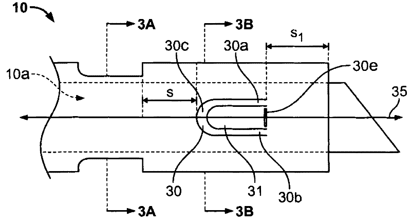
[0036] Prior art needles include needles having side openings disposed on the needle surface between the proximal and distal ends of the needle to improve the flow of fluid from the needle. However, only side openings are less efficient because typical fluid dynamics cause fluid to flow from the proximal end of the needle to the open distal end rather than through the side opening as desired.

[0037] The improved needle includes a U-shaped side hole extending through the outer surface and a corresponding shunt. The U-shaped side aperture is an opening dimensioned along the length of the needle shaft that is proportional to the size and shape of the at least one shunt. The side holes can be sized proportionally and slightly larger than the splitter. For example, a U-shaped side hole may be a slit corresponding to the contour of a U-shaped splitter. The U-shaped side holes may be shaped to minimize the turbulent component of fluid flow, thereby minimizing turbulent flow. Acc...


PUM


Abstract

A method of reducing cell damage can include inserting device into a blood vessel, wherein the device includes a hollow shaft, a lumen, a fluid directing portion comprising a U-shaped lateral orifice extending between the exterior and interior surfaces and a corresponding U-shaped diverter adjacent to the U-shaped lateral orifice, wherein the diverter is disposed within the lumen and transverse to the central axis, and decreasing free plasma hemoglobin levels, thereby reducing damage to circulating blood cells or endothelium during dialysis.

Description

[0001] This application claims priority to U.S. Provisional Application No. 61 / 101,873, filed October 1, 2008, which is International Application No. PCT / US2008 / 007866, filed June 25, 2008 Continuation-in-Part of the US Provisional Application and International Application No. PCT / US2008 / 007866 are hereby incorporated by reference in their entirety. technical field [0002] The present invention generally relates to the field of fluid delivery systems, applicable to the field of dialysis needles. Background technique [0003] Hemodialysis using a needle requires the use of two needles: one, called the arterial needle, which draws blood from the patient (or from the dialysis vessel access) and the other, called the venous needle, which returns blood to the patient. Essentially, the process produces blood that has been processed by an artificial kidney. Both needles are inserted into the dialysis access, which can be a surgically modified vein called a fistula or a graft inse...

Claims


Application Information

Patent Timeline
IPC IPC(8): A61M1/14A61M5/158
CPCA61M1/3653A61M5/158A61M2001/3661A61M1/3661A61M1/3655A61M1/3659
Inventor 阿尔佛雷德·R·扎拉特
Owner 阿尔佛雷德·R·扎拉特
Learn More