

Evaporation concentration device
A technology of evaporative concentration and evaporation tank, which is applied in the field of evaporative concentration devices, can solve the problems of reduced thermal conductivity and low heat transfer efficiency, and achieve the effect of uniform thin film evaporation
- Summary
- Abstract
- Description
- Claims
- Application Information
AI Technical Summary
Problems solved by technology
Method used
Image

Examples
Embodiment approach 1
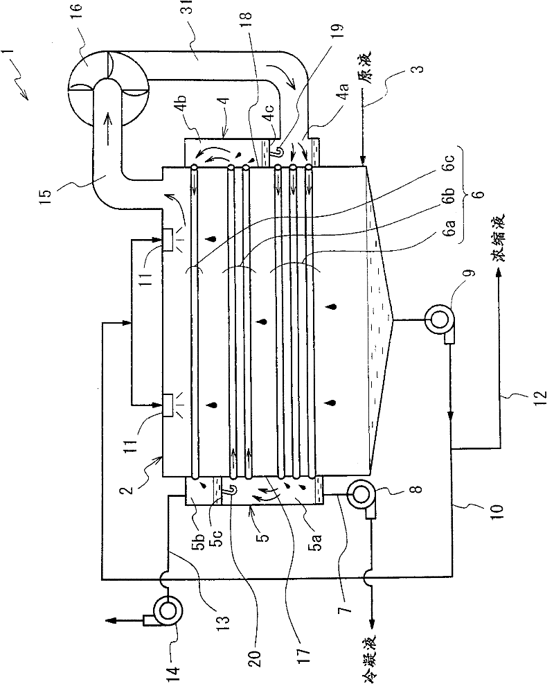
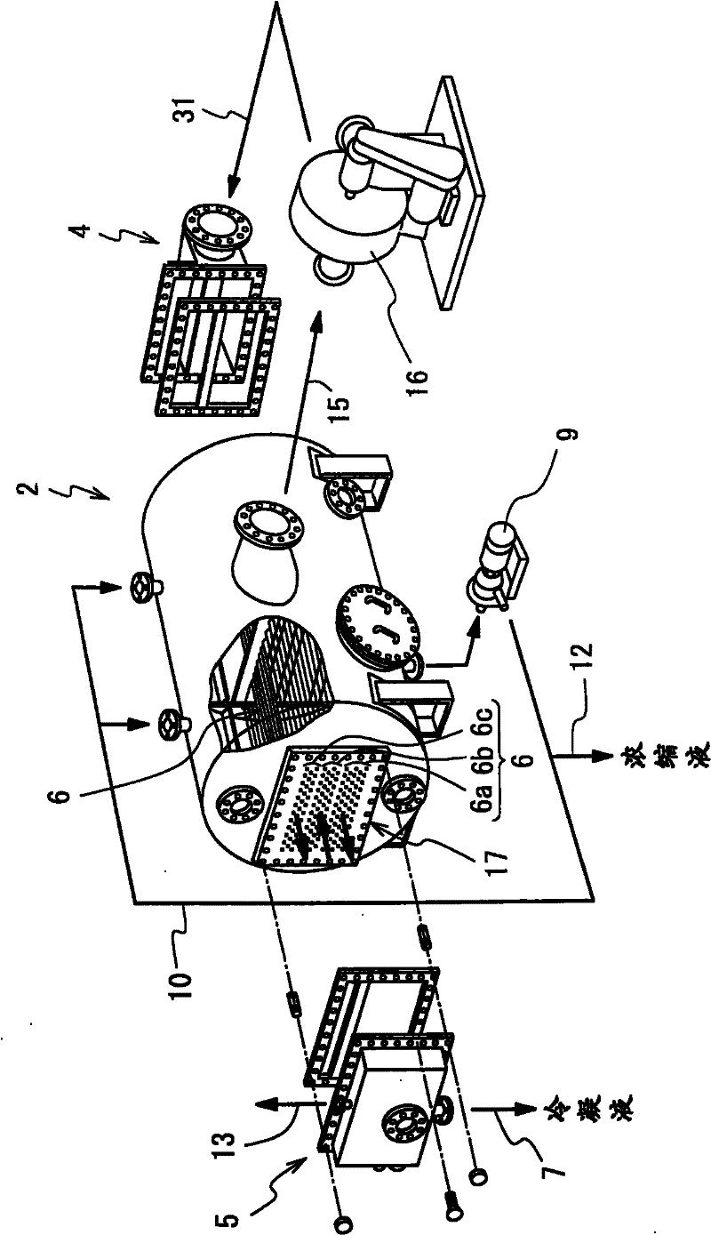
[0039] Hereinafter, the evaporation concentration device in the embodiment of the present invention will be described in detail with reference to the drawings. figure 1 A schematic configuration diagram showing the evaporation concentration device in the embodiment of the present invention, figure 2 Shows an exploded perspective view of its important parts.
[0040] This evaporative concentration device 1 includes a horizontal tube type closed evaporator 2. The solution to be concentrated (stock solution) is supplied from the stock solution supply line 3 ( figure 1 ) Is supplied to the lower part of the evaporation tank 2. A pair of header boxes 4 and header boxes 5 are provided on the left and right sides of the evaporation can 2. A plurality of heat transfer tubes 6 are horizontally erected between the header box 4 and the header box 5.
[0041] The solution in the lower part of the evaporation tank 2 is supplied to a sprayer 11 such as a nozzle provided in the upper part of th...
Embodiment approach 2
[0084] Figure 7 In order to show the structure of the evaporation concentration device 1a of other embodiment of the present invention, the figure 1 The parts with the same reference signs. At that Figure 7 In, and figure 1 Differently, the inlet side header 4 is shown on the left side, and the outlet side header 5 is shown on the right side.
[0085] The evaporative concentration device 1a of the present embodiment includes a condenser 22 that condenses vapor from the evaporator can 2.
[0086] The condenser 22 includes a plurality of heat transfer tubes 26 in the tank body 25, and includes a cooling water inlet 27 leading into the heat transfer tube 26 and a cooling water outlet 28 from the heat transfer tube 26.
[0087] The tank body 25 is connected to the turn-back chamber 5a of the header 5 on the outlet side of the evaporation tank 2 through a pipeline 29, and on the other hand, is connected to the upper part of the evaporation tank 2 and the outlet chamber of the header 5 o...
Embodiment approach
[0094] Although in each of the above-mentioned embodiments, the plurality of heat transfer tubes are divided into a plurality of heat transfer tube groups, in the vertical direction, the number of tubes in the heat transfer tube group decreases as the number of the heat transfer tube groups increases, and the heat transfer from the bottom The heat transfer tube group with the largest number of tubes supplies heating steam. However, on the contrary, in other embodiments of the present invention, the plurality of heat transfer tubes may also be divided into a plurality of heat transfer tube groups, in the vertical direction, The heat transfer tube groups are arranged so that the number of tubes in the upper heat transfer tube group increases sequentially, and heating steam is supplied from the heat transfer tube group with the largest number of tubes above.
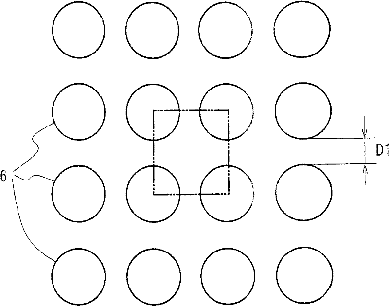
[0095] The arrangement of the heat transfer tubes 6 in addition to the above-mentioned four-corner pitch arrangement, for exa...
PUM
| Property | Measurement | Unit |
|---|---|---|
| Outer diameter | aaaaa | aaaaa |
Abstract
Description
Claims
Application Information