
Evaporation auxiliary device and drying equipment

An auxiliary device and drying technology, which is applied in the direction of lighting and heating equipment, heating devices, drying solid materials, etc., can solve the problems of uneven film thickness and affecting the display effect of organic electroluminescent display devices, etc.

Pending Publication Date: 2018-11-06
BOE TECH GRP CO LTD +1
View PDF8 Cites 3 Cited by
  • Summary
  • Abstract
  • Description
  • Claims
  • Application Information

AI Technical Summary

Problems solved by technology

Because in the drying process, the closer to the edge of the substrate, the faster the solvent volatilization speed, therefore, the solvent evaporation speed is different between the area near the center of the substrate and the area near the edge of the substrate, resulting in the difference between the middle area of ​​the substrate and the area near the edge of the substrate. The thickness of the formed film layer is uneven, which affects the display effect of the organic electroluminescence display device

Method used


Image

  • Evaporation auxiliary device and drying equipment
  • Evaporation auxiliary device and drying equipment
  • Evaporation auxiliary device and drying equipment

Examples


Embodiment 1

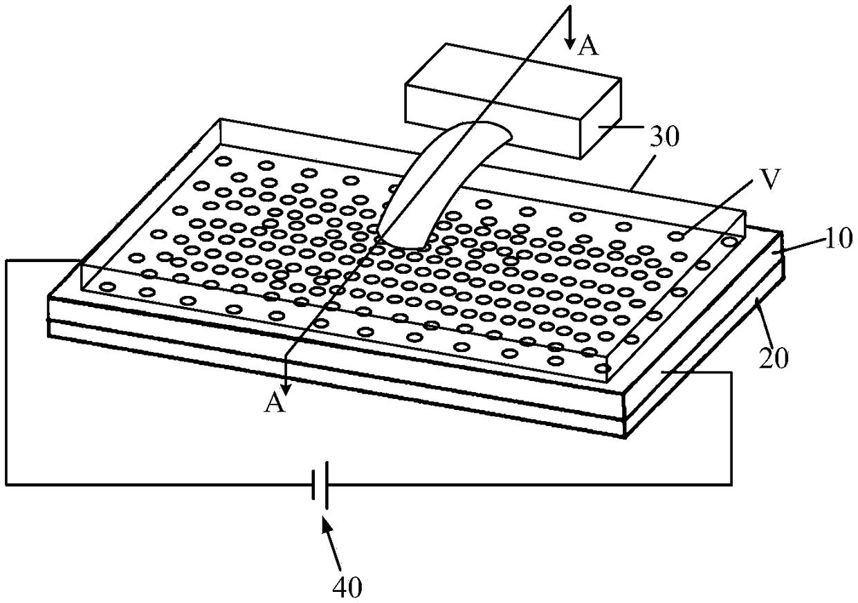
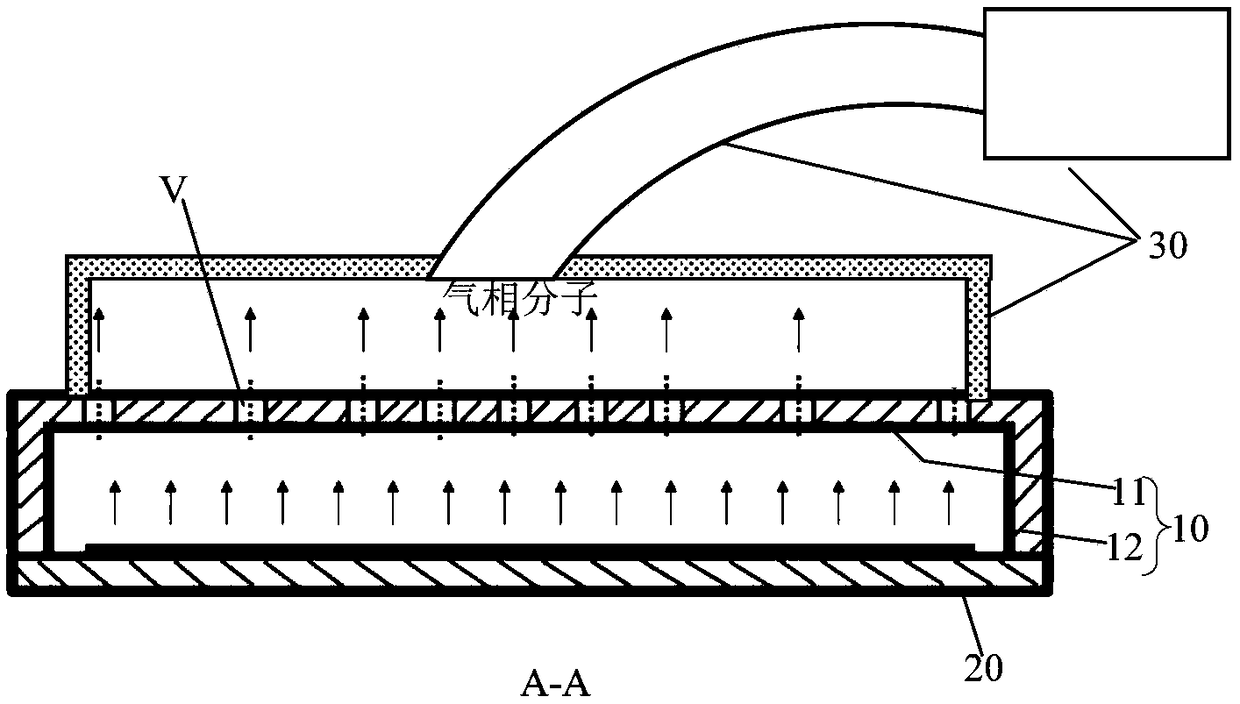
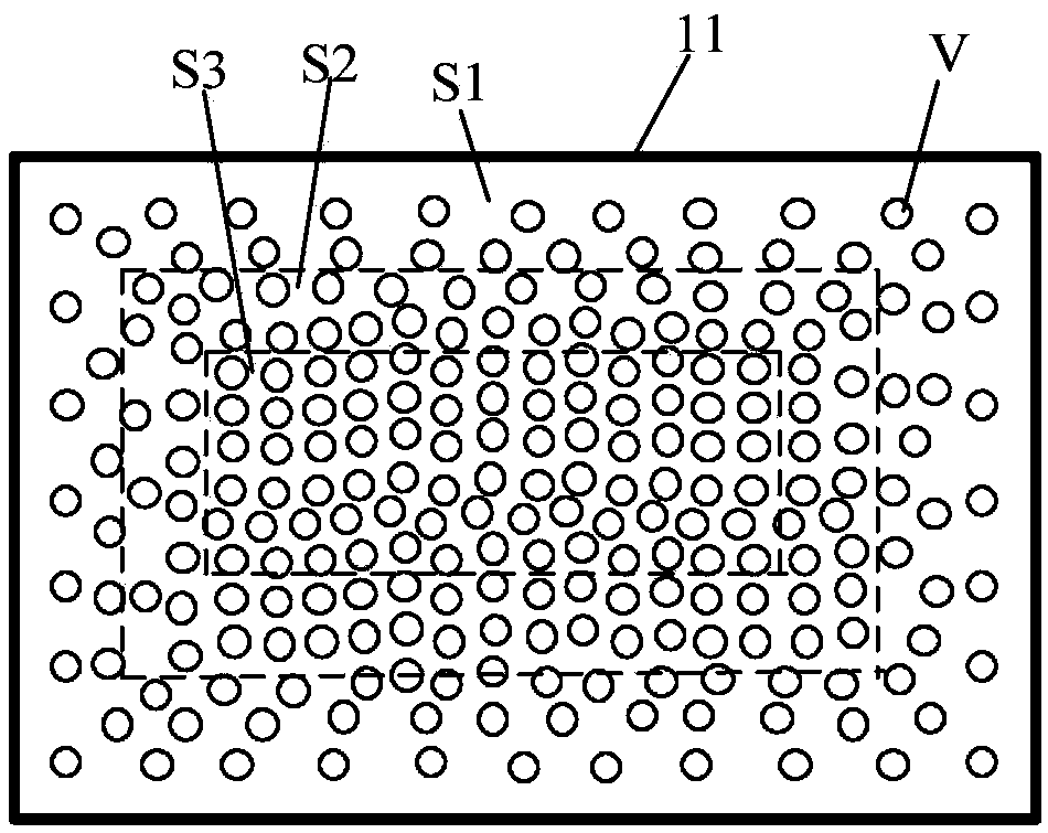
[0026] figure 1 It is a schematic diagram of the application of the evaporation auxiliary device provided in Embodiment 1 of the present invention, figure 2 is along figure 1 Sectional view of line AA in the middle, image 3 It is one of the top views of the cover plate in the evaporation auxiliary device provided by Embodiment 1 of the present invention, Figure 4 It is the second top view of the cover plate in the evaporation auxiliary device provided by the first embodiment of the present invention. The evaporation auxiliary device is used in a film layer drying process, and the film layer drying process is a process of drying the ink to form a film layer after printing the ink on the substrate. combine Figure 1 to Figure 4 As shown, the evaporation auxiliary device includes a cover plate 10, the cover plate 10 includes a top wall 11 and a side wall 12 connected to the top wall 11, the top wall 11 is used to be arranged opposite to the area to be dried of the substrat...

Embodiment 2

[0038]The evaporative auxiliary device of this embodiment is similar in structure to the evaporative auxiliary device of Embodiment 1, the only difference lies in the distribution of the ventilation holes V. Figure 5 It is a schematic diagram of the distribution of ventilation holes on the cover plate of the evaporation auxiliary device in the second embodiment of the present invention, as shown in Figure 5 As shown, the distribution density of the ventilation holes V in each ventilation area S1-S3 is the same; from the middle of the top wall 11 to the edge of the top wall 11, the opening size of the ventilation holes V in the ventilation areas gradually decreases. Wherein, in the same ventilation zone, the opening sizes of the ventilation holes V can be the same, or can be set according to the rule that the farther away from the center of the top wall 11 the smaller the openings are. use Figure 5 The method can also make the ratio of the sum of the opening areas of the ve...

Embodiment 3

[0042] Embodiment 3 provides a drying device, which includes a carrier table and the evaporation auxiliary device described in Embodiment 1 or Embodiment 2 above, and the carrier table is used to carry a substrate to be dried. The carrier table can also heat the substrate to be dried, so as to speed up the volatilization of the solvent on the substrate to be dried.

[0043] Since the above-mentioned evaporation auxiliary device is used in the film layer drying process, it can balance the volatilization rate of the solvent in the entire area to be dried of the substrate to be dried. Therefore, the drying equipment using the evaporation auxiliary device can dry different positions in the area to be dried. The thickness of the formed film layer is more uniform, so that when the substrate to be dried is used in a display device, the display effect is better.


PUM


Abstract

The invention provides an evaporation auxiliary device which is used for the film layer drying technology and comprises a shield plate, wherein the shield plate comprises a top wall and side walls connected with the top wall; the top wall is used for being arranged opposite to the to-be-dried area of a to-be-dried base plate; the side walls are used for supporting the to-be-dried base plate and surrounding the to-be-dried area; a plurality of vent holes are formed in the top plate; the top wall of the shield plate is divided into a plurality of ventilation areas distributed from the middle ofthe top wall to the edge of the top wall; and from the middle of the top wall to the edge of the top wall, the the ratio of the sum of the opening areas of the vent holes in the ventilation areas to the areas of the ventilation areas is gradually reduced. Correspondingly, the invention further provides drying equipment. According to the evaporation auxiliary device, the volatilization speed of solvent in the entire to-be-dried area can be balanced, so that the thicknesses of film layers formed after drying different positions of the to-be-dried area are more uniform.

Description

technical field [0001] The invention relates to the production field of organic electroluminescent display devices, in particular to an evaporation auxiliary device and drying equipment. Background technique [0002] The film-forming methods of organic light-emitting diode (OLED) mainly include evaporation process and solution process. The inkjet printing technology in the solution process is considered to be an important way to achieve mass production of large-sized organic electroluminescent devices due to its high material utilization rate and large-scale size. [0003] The process of inkjet printing includes inkjet printing and drying. The inkjet printing process is to print ink (that is, a solution formed by dissolving the material used to form the film layer in a solvent) on the substrate, and the drying process is to evaporate the solvent. After forming a film layer. Because in the drying process, the closer to the edge of the substrate, the faster the solvent volat...

Claims


Application Information

Patent Timeline
IPC IPC(8): F26B9/10F26B23/04F26B25/00
CPCF26B9/10F26B23/04F26B25/001
Inventor 王欣竹吴新风胡友元李菲李慧慧栾梦雨
Owner BOE TECH GRP CO LTD
Learn More