Method for manufacturing electromagnetic pipe of proportional electromagnetic valve

A manufacturing method and solenoid valve technology, applied in manufacturing tools, non-electric welding equipment, welding equipment, etc., can solve problems such as failure to effectively control the current passing area, shortage, high temperature magnetic deterioration welding strength, etc.

Inactive Publication Date: 2011-11-09
蔡承宏 +2
View PDF5 Cites 5 Cited by
  • Summary
  • Abstract
  • Description
  • Claims
  • Application Information

AI Technical Summary

Problems solved by technology

[0007] In view of the fact that if the electromagnetic tube is made by welding and cutting, there will be problems of high-temperature magnetic deterioration and insufficient welding strength, and if it is made by heating and welding, the joint end surface of the electromagnetic tube will not be able to withstand high pressure due to the limitation of the melting point of the raw materials. , prone to breakage or fracture, and neither of these two methods can effectively control the current passing area, so as to control the displacement of the valve core (SPOOL) and withstand high pressure. In order to solve the aforementioned problems, the present invention provides a proportional The electromagnetic tube manufacturing method of the solenoid valve uses the structural change of the joint end face to achieve the purpose of increasing the joint end face area, stabilizing the joint effect, and improving the high-voltage resistance characteristics, and can effectively control the attractive force of the movable iron core in the solenoid tube according to the magnitude of the current. In order to reach the required relative resistive force of the spring of the electromagnetic tube, in order to achieve the aforementioned purpose, the technical means of the present invention are as follows

Method used


Image

  • Method for manufacturing electromagnetic pipe of proportional electromagnetic valve
  • Method for manufacturing electromagnetic pipe of proportional electromagnetic valve
  • Method for manufacturing electromagnetic pipe of proportional electromagnetic valve

Examples


Embodiment Construction

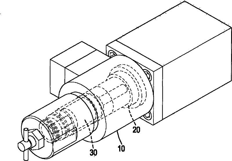
[0056] The present invention is about a method for manufacturing a solenoid tube of a proportional solenoid valve, please refer to figure 1, the proportional electromagnetic valve includes an electromagnetic coil seat 10, a solenoid tube 20 is fixed inside the electromagnetic coil seat 10, and a slidable movable iron core 30 is provided in the electromagnetic tube 20. The proportional solenoid valve is energized to the solenoid The coil in the coil seat 10 drives one of the excitation tube bodies on the solenoid tube 20 to generate a magnetic force to attract the movable iron core 30 to reciprocate in the solenoid tube 20 to achieve the purpose of controlling the opening and closing state of the circuit;

[0057] Further, the proportional solenoid valve of the present invention is based on the electric quantity of the input electromagnetic coil, which can change the magnetic size of the magnetic tube 20 excitation tube body, so as to control the displacement of the movable iro...


PUM


Abstract

The invention relates to a method for manufacturing an electromagnetic pipe of a proportional electromagnetic pipe. The method comprises the following steps of: correspondingly jointing a first joint surface of a first exciting pipe body onto a first fusion welding surface of a non-magnetic pipe body; and correspondingly jointing a second joint surface of a second exciting pipe body onto a second fusion welding surface of the non-magnetic pipe body, wherein at least one group of corresponding surfaces are mutually folded in an oblique state. Therefore, according to current size, the aims of controlling the magnitude of magnetic force, increasing the jointing surface between each exciting pipe body and the non-magnetic pipe body on the electromagnetic pipe, intensifying a jointing structure and improving high-pressure resistance can be fulfilled.

Description

technical field [0001] The invention relates to a manufacturing method of a solenoid valve assembly, in particular to a manufacturing method of a solenoid tube of a proportional solenoid valve. Background technique [0002] Solenoid valve is a kind of solenoid valve that uses coil to energize the end of the solenoid tube to generate magnetic force to attract the movable iron core (plunger) to reciprocate in the solenoid tube, thereby achieving the purpose of controlling the state of the pipeline switch with the solenoid valve. [0003] Since the reciprocating motion of the movable iron core is attracted by the magnetism generated by the excitation of the coil at both ends of the solenoid tube, the two ends of the solenoid tube must be the excitation tube body made of magnetic material, and between the two excitation tube bodies must be The non-magnetic tube body of non-magnetic material is used as the interval to control the solenoid valve to achieve unilateral attraction an...

Claims


Application Information

Patent Timeline
Patent Type & Authority Applications(China)
IPC IPC(8): B23P15/00B23K20/12
Inventor 蔡承宏松井正仁中岛和之
Owner 蔡承宏
Why Eureka
Try Eureka