Chain

A chain and end edge technology, applied in the field of low-friction chains, can solve the problems that the wedge film effect cannot be fully exerted and the sliding resistance increases, and achieve the effects of reducing the sliding contact area, reducing the resistance, and reducing the sliding contact resistance

Inactive Publication Date: 2011-11-09
TSUBAKIMOTO CHAIN CO
View PDF4 Cites 2 Cited by
  • Summary
  • Abstract
  • Description
  • Claims
  • Application Information

AI Technical Summary

Problems solved by technology

[0009] In addition, in order to solve the above-mentioned problem, after increasing the radius of curvature before and after the apex, the surface pressure near the apex can be reduced. The resistance prevents the wedge film effect from being fully exerted, so there is a problem of increased sliding resistance

Method used


Image

  • Chain
  • Chain
  • Chain

Examples


Embodiment 1

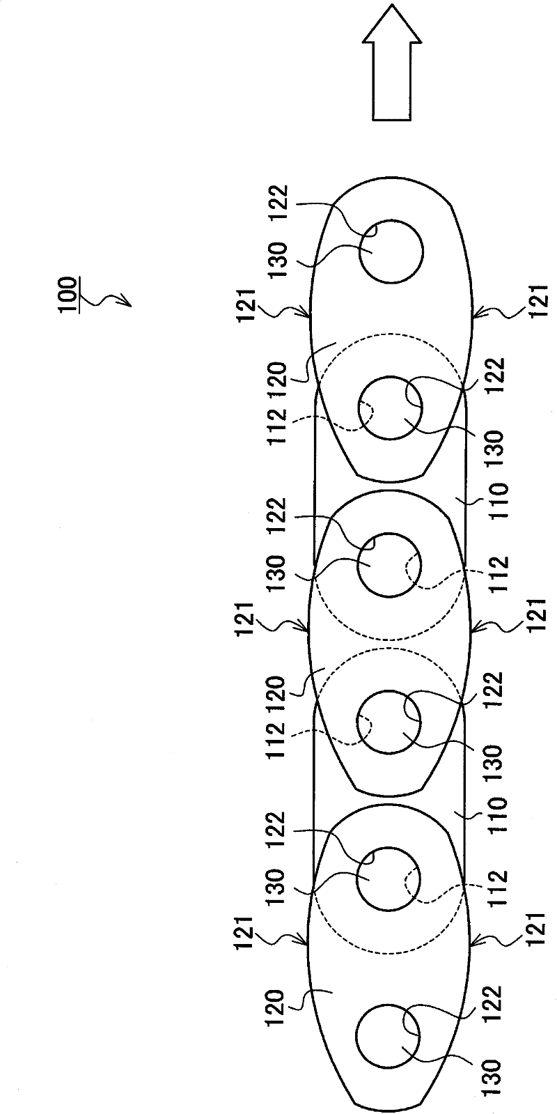
[0047] like figure 2 As shown, in the chain 100 according to the first embodiment of the present invention, a plurality of inner connecting plates 110 and outer connecting plates 120 formed with a pair of connecting holes 112 and 122 respectively are connected together by connecting pins 130 in a bendable manner .

[0048] However, as with the known chain 500 described above, it is of course possible to use a bendable sleeve chain in which the connecting pin 130 is slidably fitted in the connecting hole 112 of the inner connecting plate 110 through a fitting sleeve. A roller chain in which rollers are slidably fitted to the outer circumference of a sleeve.

[0049] The upper and lower end edges of the outer connecting plate 120 are convex end edges 121, which are formed into a convex shape composed of continuous curves, and are guided by sliding contact in the running direction of the chain; the upper and lower end edges of the inner connecting plate 110 are not guided by sl...

Embodiment 2

[0059] The chain of the second embodiment of the present invention will be described in detail below.

[0060] The chain of the second embodiment of the present invention has the same structure as the first embodiment, and the shape of its outer connecting plate is different.

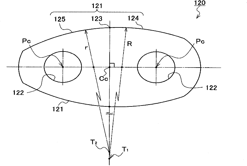
[0061] like Figure 5 As shown, in the outer connecting plate 220 of the chain according to the second embodiment of the present invention, the distance between the vertex 223 of the convex end edge 221 and the center Pc of the front and rear connecting holes 222 is equal, that is, the convex end edge The vertex 223 of the 221 is located on the vertical line of the middle point Cc of the connecting line between the front and rear connecting holes 222 .

[0062] In addition, on the curved convex edge 221 of the outer link plate 220 which is guided by sliding contact, from the vertex 223, the front edge 224 is located on the front side in the direction of travel of the chain, and the vicinity of the vert...


PUM


Abstract

The invention provides a chain which enables to effectively reduce sliding contact resistance and wear of the parts that come into sliding contact. The chain (100) comprises multiple link plates (110), (120) which, with front and rear pin holes, are rotatably interconnected and are slidingly contacted by a guide member (150). The edge (121) of at least one link plate (120) that comes into sliding contact forms a convex curvature with continuous curvatures in the direction the chain is extended. Meanwhile, the apex (123) of the edge (121) of the convex curvature is located at a position equidistant from centers of the front and rear pin holes. The convex edge (121) has different curvatures on front and rear sides of the apex.

Description

technical field [0001] The invention relates to a low-friction chain used in power transmission mechanisms such as industrial machinery or chain transmission devices such as conveying machinery, in particular to a low-friction chain suitable for timing transmission system chains of automobile engines. Background technique [0002] In power transmission mechanisms or conveyance machines of automobiles, industrial machines, and the like, a transmission device that transmits power by means of a chain spanned over a drive sprocket and a driven sprocket is generally disposed. [0003] For example, in an automobile engine, there is a timing transmission system that relies on a chain mounted on a crankshaft sprocket (drive sprocket) and a camshaft sprocket (driven sprocket) for power transmission. and other guide members sliding contact. [0004] These chains are formed of a plurality of connecting plates formed with a pair of pin-fixing holes, which are shifted in the chain lengt...

Claims


Application Information

Patent Timeline
IPC IPC(8): F16G13/06F16G15/12
CPCF16G13/02F16G13/18
Inventor 栗原和义
Owner TSUBAKIMOTO CHAIN CO
Why Eureka
Try Eureka