
Low-pressure micro-flow pressure reducing valve for space water sublimator

A sublimator, micro-flow technology, applied in valve details, valve devices, safety valves, etc., can solve the problems of high pressure control accuracy, low pressure adjustment range, and extremely small flow requirements, achieving compact size and reducing slippage. Contact area, the effect of alleviating extreme low temperature

Active Publication Date: 2021-05-18
HARBIN INST OF TECH
View PDF5 Cites 0 Cited by
  • Summary
  • Abstract
  • Description
  • Claims
  • Application Information

AI Technical Summary

Problems solved by technology

[0003] The working environment (vacuum condition, extreme temperature) of the low-pressure micro-flow pressure reducing valve used in the space water sublimator is harsh, the pressure adjustment range is low (10-10kPa), the pressure control accuracy is high (1kPa), and the flow demand is extremely small (10-30mg / s), the water resource itself is extremely precious, and the pressure reducing valve produced in the market can no longer meet its related needs

Method used


Image

  • Low-pressure micro-flow pressure reducing valve for space water sublimator
  • Low-pressure micro-flow pressure reducing valve for space water sublimator
  • Low-pressure micro-flow pressure reducing valve for space water sublimator

Examples


specific Embodiment approach 1

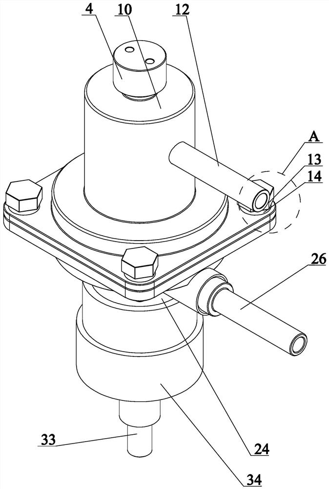
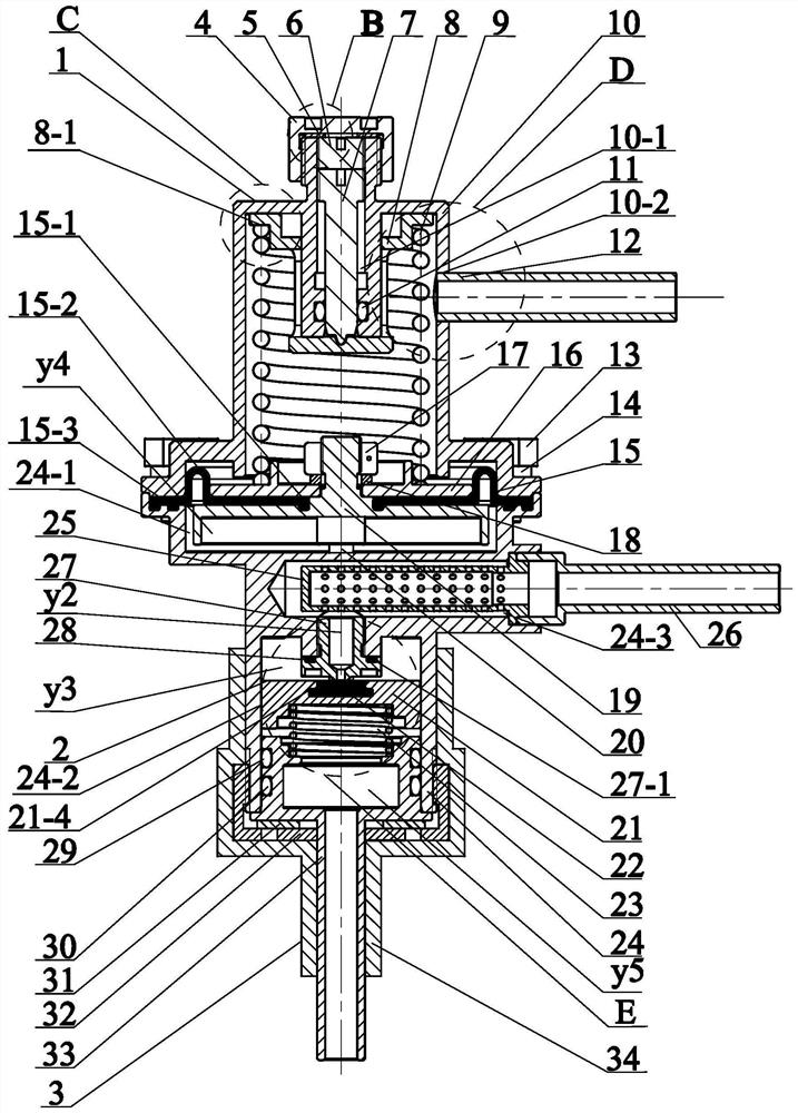
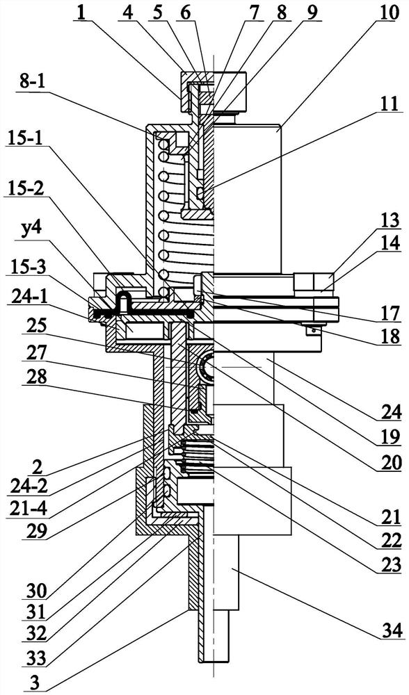
[0031] Specific implementation mode one: as Figure 1-Figure 13 As shown, this embodiment discloses a low-pressure micro-flow pressure reducing valve for a space water sublimator, including an upper housing assembly 1, a diaphragm valve core assembly 2 and a lower housing assembly 3;

[0032] The upper housing assembly 1 includes a pressure regulating end cover 4, a pressure regulating pipe locker 6, a pressure regulating rod 7, a pressure regulating plate 8, a pressure regulating spring 9, an upper casing 10 and a ventilation pipe 12;

[0033] The diaphragm spool assembly 2 includes a diaphragm assembly and a spool assembly, and the diaphragm assembly includes a diaphragm 15, a diaphragm upper stopper 16, a nut 17, a diaphragm guide seat 19 and two push rods 20; The valve core assembly includes a valve core 21, a valve port matching body 22 and a return spring 23;

[0034] The lower casing assembly 3 includes a lower casing 24, a filter 25, a water inlet pipe 26, a nozzle 27...

specific Embodiment approach 2

[0039] Specific implementation mode two: as figure 2 , image 3 As shown, this embodiment is a further description of specific embodiment 1. The middle part of the top wall of the upper casing 10 is respectively provided with a downwardly extending boss 1 and an upwardly extending boss 2, and the boss 1 and The middle part of the boss two is provided with a connected upper center hole 10-1, and the pressure regulating rod 7 is arranged in the upper center hole 10-1 of the upper casing 10 and the two are screwed (the upper center hole of the upper casing 10 The upper end of the inner wall of 10-1 is provided with internal threads, and the outer wall of the upper end of the pressure regulating rod 7 is provided with external threads); the pressure regulating pipe locker 6 is arranged in the upper center hole 10-1 of the upper casing 10 and both Threaded connection (the outer wall of the regulator tube locker 6 is provided with an external thread, and the regulator tube locker ...

specific Embodiment approach 3

[0040] Specific implementation mode three: as figure 2 , image 3 and Figure 11 As shown, this embodiment is a further description of the second specific embodiment. The central hole of the pressure regulating plate 8 is fixedly set on the upper end of the outer side of the boss one, and the outer periphery of the pressure regulating plate 8 is provided with an outer step 8-1 , the upper end of the pressure regulating spring 9 leans against the end face of the outer step 8-1 of the pressure regulating plate 8.


PUM


Abstract

The utility model relates to a low-pressure micro-flow reducing valve for a space water sublimator, which belongs to the field of aerospace water pressure valves. The upper part of the upper shell is provided with a pressure regulating rod, a pressure regulating plate and a pressure regulating spring. The spring force of the pressure regulating spring is adjusted by adjusting the screwing length of the pressure regulating rod. Between the housings, the diaphragm upper limit plate is pressed against the upper part of the diaphragm, and the diaphragm guide seat is pressed against the lower part of the diaphragm. The outer ring surface of the diaphragm guide seat is provided with radially evenly distributed prisms one, and the outer ring surface of the valve core is provided with There are two radially evenly distributed prisms, the blind hole in the middle of the valve core is installed into the valve port fitting, the nozzle and the valve port fitting form a hard-soft fitting form, and the upper and lower ends of the valve core are dynamically balanced under the force of the push rod and the return spring , to ensure that the characteristics of the valve port of the pressure reducing valve are within the expected requirements, the upper end of the outlet pipe is arranged in the lower shell, and the lower shell is covered with a heating pipe. The present invention is not only suitable for low-pressure, micro-flow and high-precision space demand environment, but also suitable for land operations.

Description

technical field [0001] The invention belongs to the field of aerospace hydraulic valves, and in particular relates to a low-pressure micro-flow pressure reducing valve for a space water sublimator. Background technique [0002] The low-pressure and small-flow pressure reducing valves used in the existing engineering field generally use pressure-regulating springs as adjustment elements. The pressure adjustment range of the direct-acting pressure reducing valve is generally in the MPa range, and the pressure control accuracy is between 10% and 15%. The magnitude of the flow working range is liters per minute. When the pressure control accuracy is high and the flow demand is large, the pressure reducing valve can be considered to be designed as a pilot type structure. [0003] The working environment (vacuum condition, extreme temperature) of the low-pressure micro-flow pressure reducing valve used in the space water sublimator is harsh, the pressure adjustment range is low (...

Claims


Application Information

Patent Timeline
Patent Type & Authority Patents(China)
IPC IPC(8): F16K17/32F16K31/365
CPCF16K17/32F16K31/365
Inventor 杨庆俊敖之宾刘钰栋朱家龙朱瑞张葭董日治刘宇辉毛奇
Owner HARBIN INST OF TECH
Learn More