Ultrahigh pressure testing system and control method thereof
A control method and ultra-high pressure technology, applied in the direction of fluid pressure control, electric fluid pressure control, non-electric variable control, etc., can solve the problem of not being able to comprehensively and accurately detect the performance and quality level of pressure-bearing products, and pressure detection of pressure-holding accuracy. The range does not meet the actual requirements, product reliability, stability and application field limitations, etc., to achieve the effect of reliable installation, large pressure range, and stable boost
- Summary
- Abstract
- Description
- Claims
- Application Information
AI Technical Summary
Problems solved by technology
Method used
Image
Examples
Embodiment 1
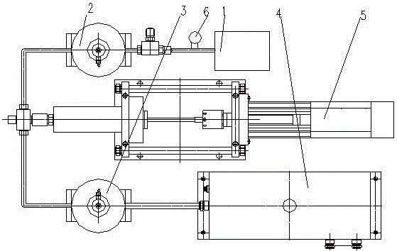
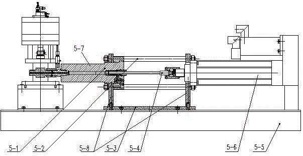
[0065] like figure 1 and figure 2 The ultra-high pressure test system shown includes: a first control valve 3, a second control valve 2, a liquid tank 4 and a servo booster 5, and the liquid tank 4 is connected to the first control valve 3, servo Supercharger 5, second control valve 2 and pressure test device 1, a second pressure detection module is provided between the second control valve 2 and pressure test device 1, the connection between the first control valve 3 and the second control valve 2 There is a first pressure detection module between them, the first pressure detection module can also be set in the high pressure cylinder 5-1, the first control valve 3 and the second control valve 2 are forced open / close valves, which can be used instead of traditional pressure test pumps The water pressure automatically opens the valve, and the second control valve 2 is also provided with a pressure gauge 6 on the pipeline connected to the liquid tank 4, and the pressure gauge ...
Embodiment 2
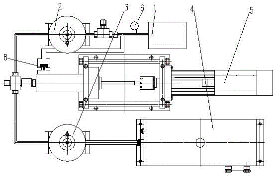
[0076] like figure 2 and image 3 The ultra-high pressure test system shown includes: a liquid tank 4, a first control valve 3 and a servo booster 5, the liquid tank 4 is connected with the first control valve 3 and the servo booster 5 in turn, and the servo booster 5 A pressure test device 1 is connected, and a second control valve 2 is provided between the servo booster 5 and the pressure test device 1; the servo booster 5 is connected to the pressure test device 1 through a liquid outlet pipe, and the outlet pipe is provided with a Liquid valve 8.
[0077] A first pressure detection module is provided between the first control valve 3 and the second control valve 2 or in the servo booster 5, and the first pressure detection module is preferably located between the first control valve 3 and the second control valve 2 The pipeline between them is used to measure the pressure applied by the servo booster 5; a first Two pressure detection modules, the second pressure detect...
Embodiment 3
[0086] like figure 2 and Figure 4 The ultra-high pressure test system shown includes: a liquid tank 4, a first control valve 3 and a servo booster 5, the liquid tank 4 is connected with the first control valve 3 and the servo booster 5 in turn, and the servo booster 5 A pressure test device 1 is connected, and a second control valve 2 is provided between the servo booster 5 and the pressure test device 1; the servo booster 5 is connected to the liquid tank 4 through a liquid inlet pipe, and a liquid inlet pipe is provided on the liquid inlet pipe. valve 7.
[0087] A first pressure detection module is provided between the first control valve 3 and the second control valve 2 or in the servo booster 5 or between the liquid inlet valve 7 and the servo booster 5, and the first pressure detection module is preferably set On the pipeline between the first control valve 3 and the second control valve 2, it is used to measure the pressure applied by the servo booster 5; between th...
PUM
 Abstract
Description
Claims
Application Information
 - R&D
- Intellectual Property
- Life Sciences
- Materials
- Tech Scout
- Unparalleled Data Quality
- Higher Quality Content
- 60% Fewer Hallucinations
Browse by: Latest US Patents, China's latest patents, Technical Efficacy Thesaurus, Application Domain, Technology Topic, Popular Technical Reports.
© 2025 PatSnap. All rights reserved.Legal|Privacy policy|Modern Slavery Act Transparency Statement|Sitemap|About US| Contact US: help@patsnap.com


