

Flow passage unit
- Summary
- Abstract
- Description
- Claims
- Application Information
AI Technical Summary
Benefits of technology
Problems solved by technology
Method used
Image

Examples
first embodiment
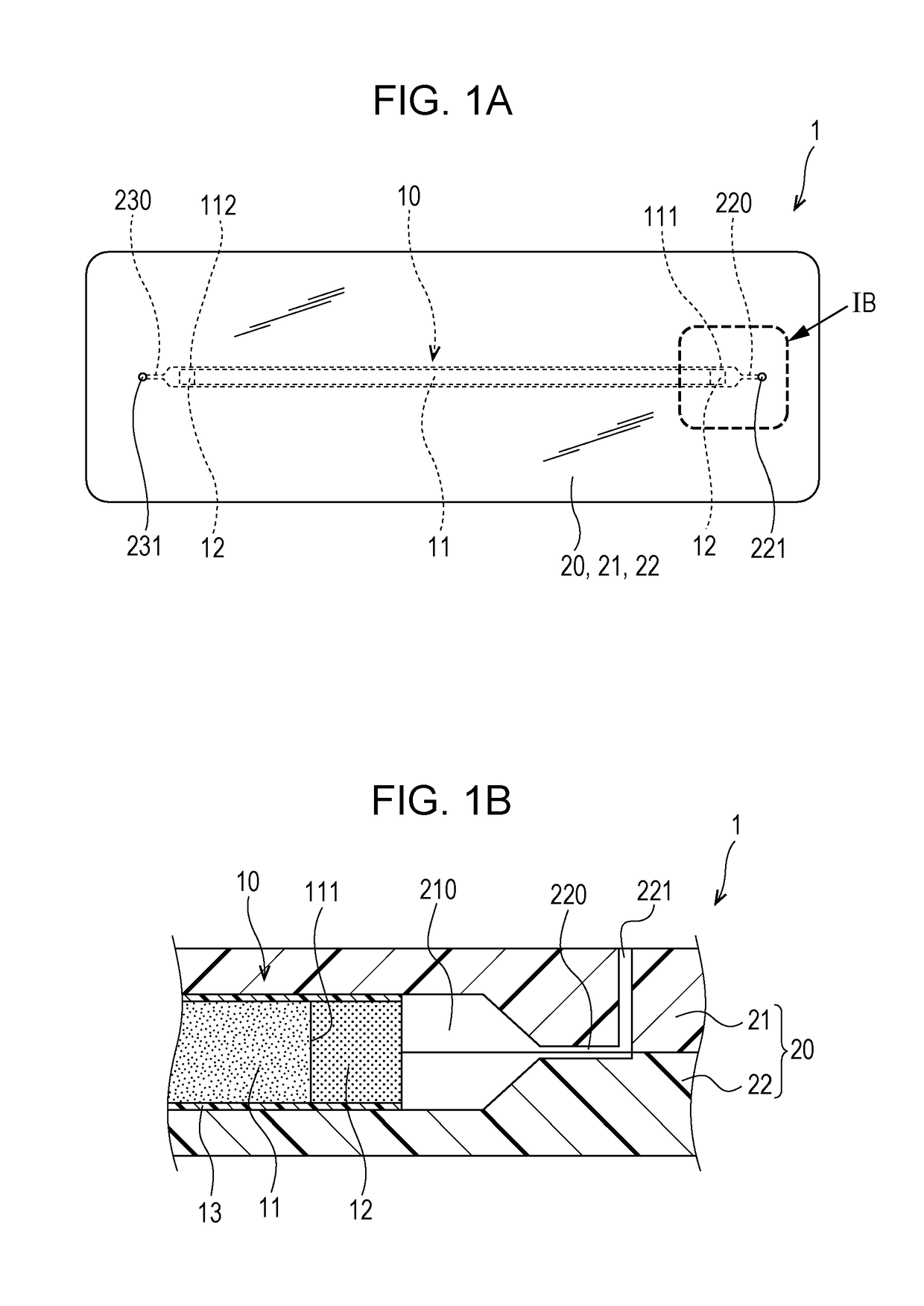
[0028]FIGS. 1A and 1B are schematic diagrams illustrating a flow passage unit according to a first embodiment.
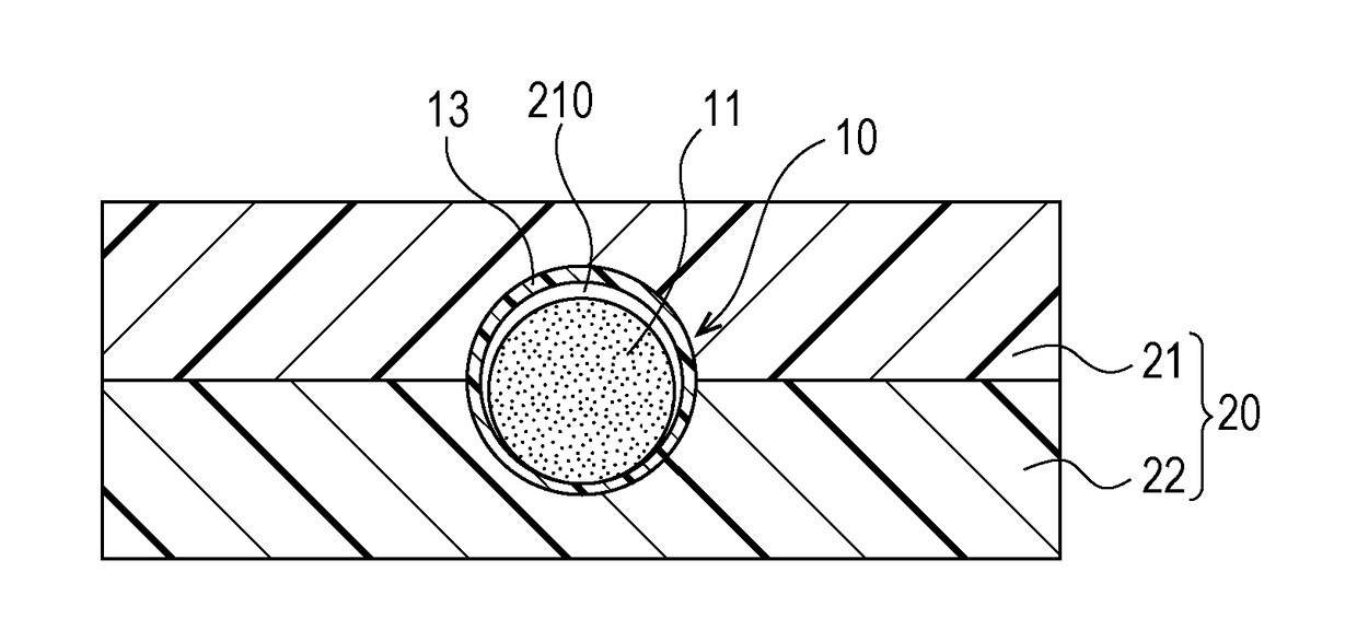
[0029]FIG. 1A is a plan view of the flow passage unit 1. FIG. 1B is an enlarged cross-sectional view of the portion IB indicated in FIG. 1A.
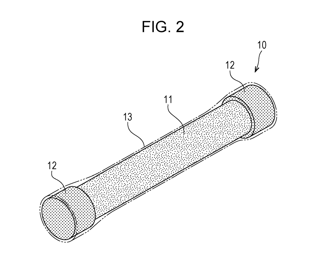
[0030]FIG. 2 is a schematic perspective view illustrating a column. In FIG. 2, for convenience of explanation, a covering part 13 is indicated by a dash-dot-dot line.
[0031]As indicated in FIGS. 1A and 1B, the flow passage unit 1 according to this embodiment has a column 10 for use in a liquid chromatograph and also has a support body 20 that supports the column 10.
[0032]The column 10 has a stationary phase 11, which has a columnar outside shape and is porous, a pressure adjusting part 12, which is provided at least at the flow-in end 111 of the stationary phase 11, a liquid entering the flow-in end 111, and has a columnar outside shape and is porous, and the covering part 13 that covers the stationary phase 11 and pressure adjusting part...
first example
[0074]FIG. 7 illustrates a liquid chromatogram obtained by using a flow passage unit according to a first example.
[0075]Measurement conditions in high performance liquid chromatography (HPLC) are as follows.
[0076]These measurement conditions are also applied to the examples and comparative examples described below.
[0077]Analyzing apparatus: LC-2010AHT manufactured by Shimadzu Corporation
[0078]Sample: uracil, methyl benzoate, toluene, and naphthalene
[0079]Amount of injection: 0.2 μL
[0080]Column oven temperature: 25° C.
[0081]Mobile phase: Acetonitrile / water=60 / 40 (vol / vol)
[0082]Detection: UV detector, 254 nm, semi-micro cell
[0083]In the first example, a structure as described below is used as the flow passage unit.
[0084]If the maximum diameter of the stationary phase portion is denoted a1, the minimum diameter of the pressure adjusting portion is denoted b2, and the inner diameter of the column holding part 210 is denoted c, then b2−c is +40 micrometers (μm) and a1−c is −48 μm. The fl...
second example
[0086]FIGS. 8A and 8B illustrate liquid chromatograms obtained by using a flow passage unit according to a second example.
[0087]In the second example, a structure as described below is used as the flow passage unit.
[0088]If the maximum diameter of the stationary phase portion is denoted a1, the minimum diameter of the pressure adjusting portion is denoted b2, and the inner diameter of the column holding part 210 is denoted c, then b2−c is +21 μm and a1−c is −41 μm.
[0089]FIG. 8A illustrates a liquid chromatogram in a case in which the flow rate of the liquid to the flow passage unit according to the second example is 0.4 ml / min.
[0090]In this example, the theoretical plate number is 13335, the symmetry factor is 1.083, and withstand pressure is 7.1 MPa.
[0091]FIG. 8B illustrates a liquid chromatogram in a case in which the flow rate of the liquid to the flow passage unit according to the second example is 0.6 ml / min.
[0092]In this example, the theoretical plate number is 12697, the symm...
PUM
| Property | Measurement | Unit |
|---|---|---|
| Pressure | aaaaa | aaaaa |
| Pressure | aaaaa | aaaaa |
| Pressure | aaaaa | aaaaa |
Abstract
Description
Claims
Application Information