Pressure equalising device for systems through which fluid flows

A pressure compensation and fluid technology, applied in the field of pressure compensation devices

Inactive Publication Date: 2011-11-09
派克汉尼汾欧洲有限责任公司(卢森堡)瑞士分公司(埃图瓦)
View PDF8 Cites 17 Cited by
  • Summary
  • Abstract
  • Description
  • Claims
  • Application Information

AI Technical Summary

Problems solved by technology

[0015] Even if the device does not require valves and thus has a simplified design, it still has the disadvantage that different sizes of inflow and outflow surfaces need to be realized by means of an odd number of guide surfaces arranged in a star shape, which is also technically demanding in manufacture

Method used


Image

  • Pressure equalising device for systems through which fluid flows
  • Pressure equalising device for systems through which fluid flows
  • Pressure equalising device for systems through which fluid flows

Examples


Embodiment Construction

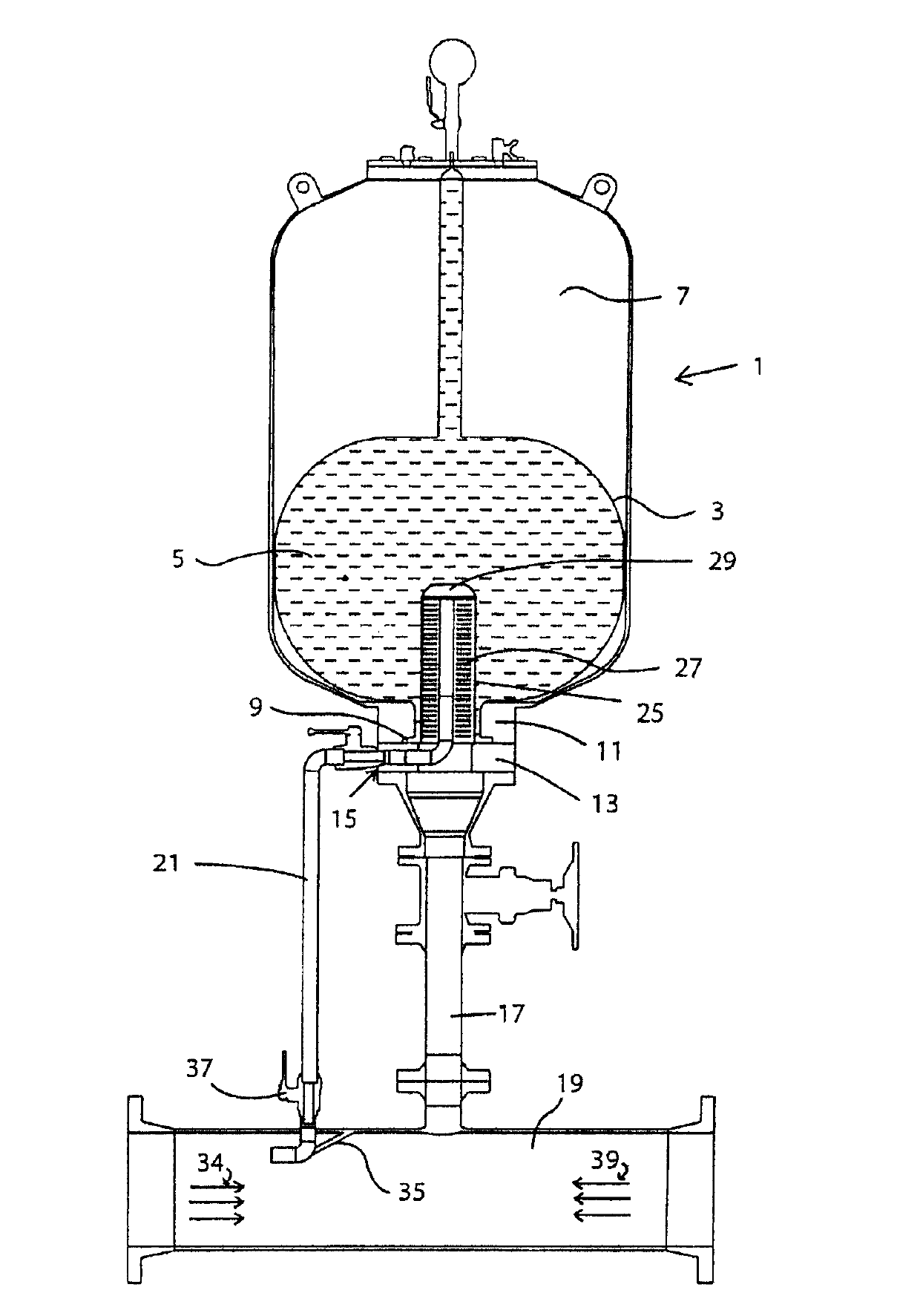
[0035] exist figure 1 A pressure compensating device for a fluid-conducting system is shown in , which comprises a pressure vessel, which is designated as a whole by the reference number 1 . An elastic membrane 3 is positioned in the pressure vessel, the membrane 3 being designed as a bladder-like membrane which defines a cavity 5 which is at least partially filled with a fluid flowing through the system. In order to explain the pressure compensation device according to the invention, this embodiment is shown by way of example but not limitation with reference to a drinking water supply. For this purpose, the elastic membrane 3 is made of rubber suitable for food. A pressure chamber filled with gas 7 is located above the diaphragm 3 delimiting the cavity 5 . Nitrogen is used here as the gas. However, other gases may also be used, such as air or a combination of two or more different gases. The nitrogen gas filling the chamber forms a buffer zone that can be used to absorb ...


PUM


Abstract

The invention relates to a pressure compensating device for fluid-conducting systems, with a pressure container (1) for the pressure compensation, an elastic diaphragm (3), which forms a cavity (5) for receiving the fluid, and a pressure chamber of gas (7) adjoining the cavity (5). The diaphragm (3) is connected via a connecting mount (15) to a connecting pipe (17) for the fluid. A pipe (21) for the fluid, led separately to the connecting pipe (17), extends via the connecting mount (15) into the cavity (5), while being concentrically encircled by a hollow cylinder (25) shaped like a sieve, which defines an annular space (27) and opens into an end piece (29), into which the pipe (21) opens. Moreover the end piece (29) features sieve-like perforations (31) for the fluid to flow out into the cavity (5). The separately led pipe (21) extends into the fluid-conducting system, while the connecting pipe (17) for the fluid opens into the fluid-conducting system.

Description

technical field [0001] The invention relates to a pressure compensating device for a fluid conducting system, comprising a pressure vessel for pressure compensation having an elastic diaphragm forming a cavity for receiving a fluid, and a pressurized diaphragm adjoining said cavity. A gas chamber, and the diaphragm is connected to a connection pipe for fluid through a connection base. Similarly, the present invention relates to preferred applications of such pressure compensation devices. [0002] Such a pressure compensating device can be used as an attenuator against hydraulic shocks and for reducing fluctuations in pipes carrying water, waste water or other fluid media, etc. Background technique [0003] Hydraulic shocks (water hammer / liquid hammer phenomenon) in piping systems such as water supply pipes and wastewater treatment pipes are sinusoidal pressure waves that can be caused by a sudden release or interruption of water flow because water is incompressible. Hydra...

Claims


Application Information

Patent Timeline
Patent Type & Authority Applications(China)
IPC IPC(8): F16L55/00
CPCF24D3/1008F16L55/053F24D3/1041F24D3/1016
Inventor P·施内德C·阿厄比施尔
Owner 派克汉尼汾欧洲有限责任公司(卢森堡)瑞士分公司(埃图瓦)
Why Eureka
Try Eureka