Display and input device
An input device and display area technology, applied in the input/output process of data processing, keyboard coding, instruments, etc., can solve problems such as difficult identification of icons, achieve excellent operability, no sense of incongruity, and simple control
- Summary
- Abstract
- Description
- Claims
- Application Information
AI Technical Summary
Problems solved by technology
Method used
Image
Examples
Embodiment approach 1
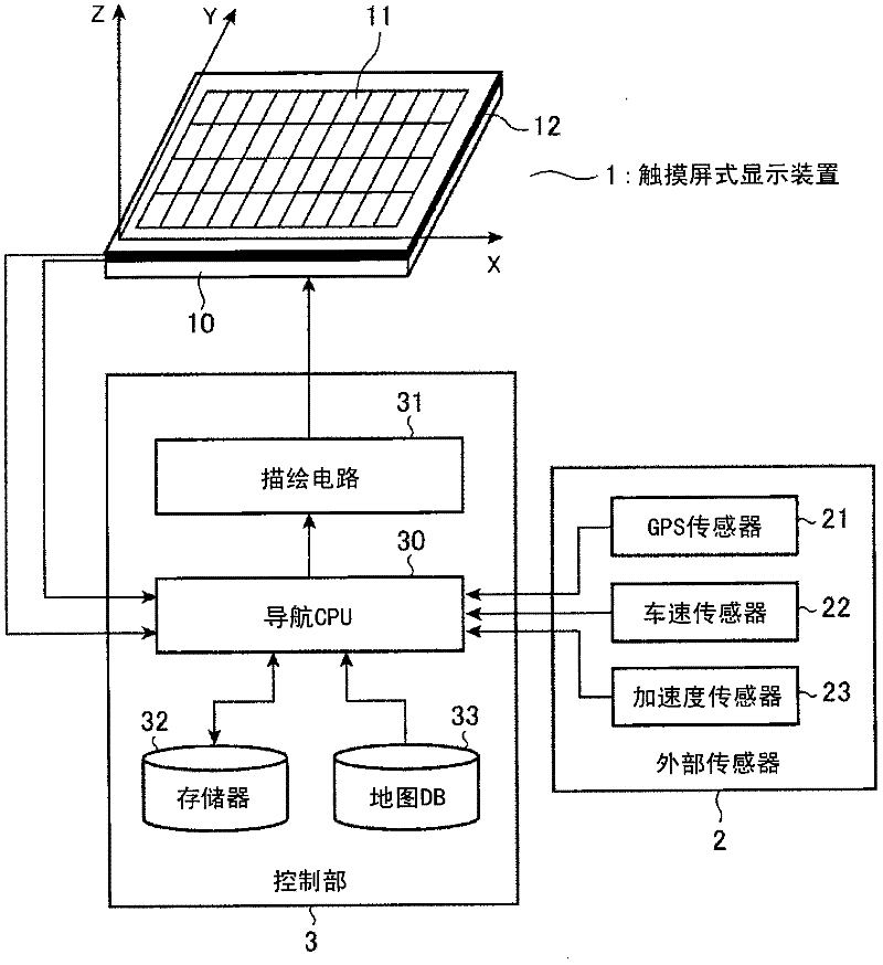
[0026] figure 1 It is a block diagram showing the configuration of the display input device according to Embodiment 1 of the present invention. Such as figure 1 As shown, the display input device according to Embodiment 1 of the present invention includes a touch panel display device (hereinafter simply referred to as a touch panel) 1 , an external sensor 2 , and a control unit 3 .
[0027] The touch screen 1 is a device for displaying and inputting information. For example, it adopts a structure in which touch sensors 11 for information input are stacked on an LCD panel 10 for information display. A plurality of proximity sensors 12 for two-dimensional non-contact detection of motions of the touch screen 1 and a finger, a pen, etc. positioned opposite to the touch screen 1 .
[0028] In the case where the proximity sensor 12 uses infrared rays, for example, infrared light-emitting LEDs (Light Emitted Diodes) and phototransistors are arranged in a matrix on the outer periphe...
Embodiment approach 2
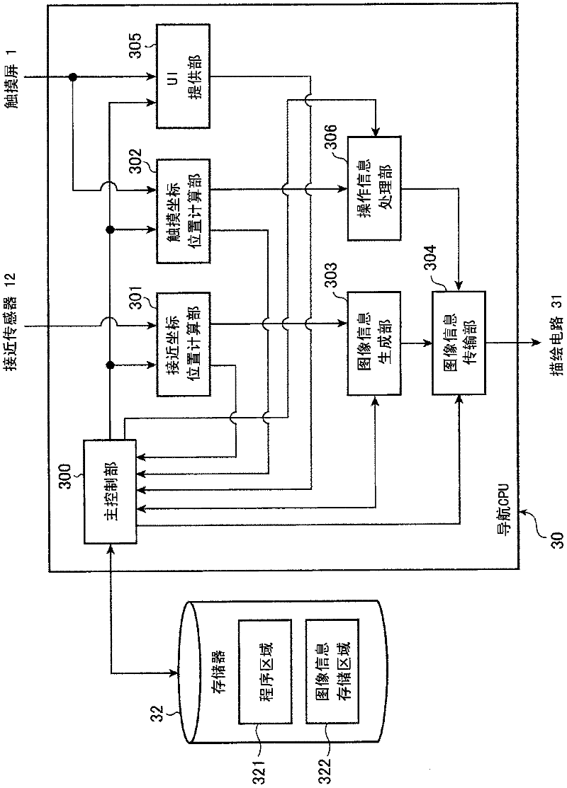
[0070] Figure 7 It is a block diagram showing the structure of a program executed by the navigation CPU 30 included in the display input device (control unit 3 ) according to Embodiment 2 of the present invention, in functional expansion.
[0071] In the display input device according to Embodiment 2 of the present invention, the figure 2 The first embodiment shown is different in that a display attribute information generation unit 307 is added to the program configuration of the navigation CPU 30 in the first embodiment except for the UI provision unit 305 .
[0072] In order to process the external icon displayed on the touch screen 1 so as to distinguish it from the internal icon, the display attribute information generating unit 307, under the control of the main control unit 300, generates an image for each image generated by the image information generating unit 303 The information generates attribute information, and the attribute information is attribute informatio...
Embodiment approach 3
[0087] Figure 10 It is a flowchart showing the operation of the display input device according to Embodiment 3 of the present invention. In addition, in Embodiment 3 described below, it is assumed that the same as Embodiment 1, using the same as figure 1 shows the same structure as the display input device, additionally, using the same structure as the figure 2 The program structure shown is the same structure.
[0088] However, the display input device according to Embodiment 3 described here is a display input device suitable for a three-dimensional touch panel capable of measuring the distance between the panel surface and the finger along the Z direction. Therefore, the figure 1 The shown touch panel 1 capable of detecting the position in the XY direction is replaced with a three-dimensional touch panel capable of measuring the distance along the Z direction. The aforementioned Patent Document 2 discloses a technique for measuring a three-dimensional position, and he...
PUM
 Abstract
Description
Claims
Application Information
 - R&D
- Intellectual Property
- Life Sciences
- Materials
- Tech Scout
- Unparalleled Data Quality
- Higher Quality Content
- 60% Fewer Hallucinations
Browse by: Latest US Patents, China's latest patents, Technical Efficacy Thesaurus, Application Domain, Technology Topic, Popular Technical Reports.
© 2025 PatSnap. All rights reserved.Legal|Privacy policy|Modern Slavery Act Transparency Statement|Sitemap|About US| Contact US: help@patsnap.com


