
Stretcher

A technology of drawing machine and drawing die, which is applied in the field of wire drawing manufacturing equipment, can solve the problems of low drawing precision, low production efficiency, and low yield, and achieve the effects of improving product quality, reducing energy consumption, and reducing consumption

Inactive Publication Date: 2014-09-10
湖北省麻城市镡鑫科技有限公司
View PDF8 Cites 3 Cited by
  • Summary
  • Abstract
  • Description
  • Claims
  • Application Information

AI Technical Summary

Problems solved by technology

[0003] The purpose of the present invention is to overcome the problems of low wire drawing precision, low yield, high energy consumption, high cost and low production efficiency in the above-mentioned existing stretching machines, and provide a stretching machine that can reduce operating links and improve Production efficiency, reducing various energy consumption, reducing costs, and improving product quality

Method used


Image

  • Stretcher
  • Stretcher

Examples


Embodiment Construction

[0016] The stretching machine of the present invention will be described in detail below in conjunction with the accompanying drawings and examples.

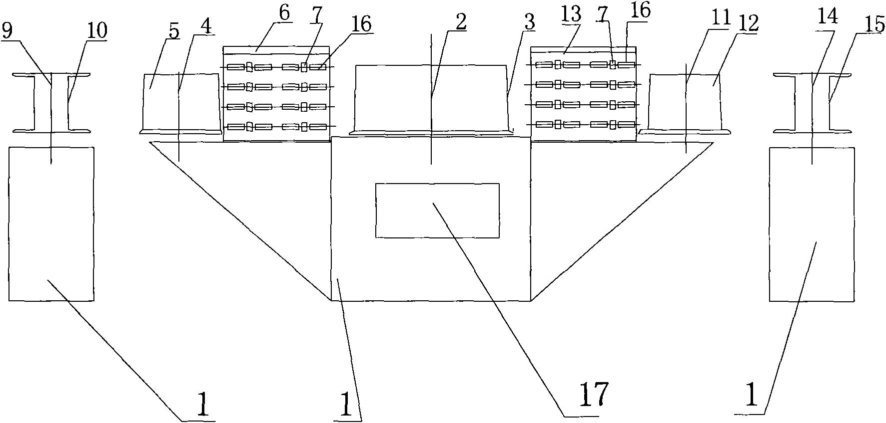
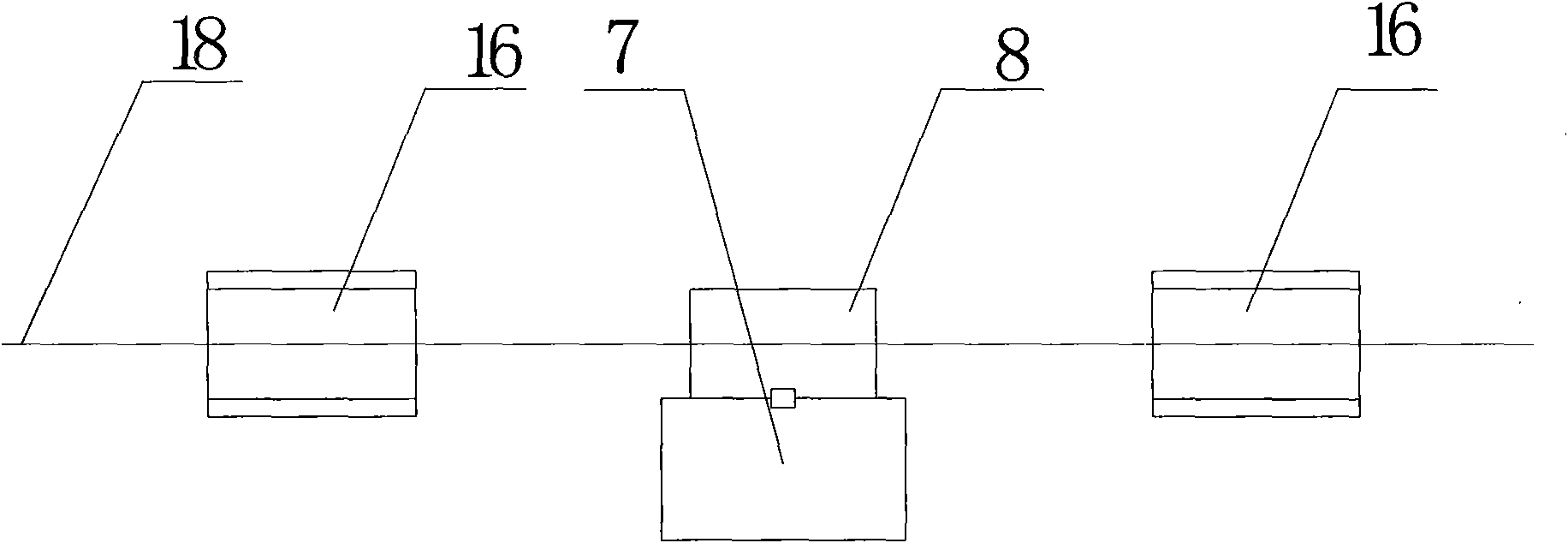
[0017] Such as figure 1 Shown, is a kind of drawing machine provided by the present invention, and its structure at least includes fuselage 1, drive shaft 2 and drive disc 3, first driven shaft 4 and first driven disc 5, first formwork 6, Drawing die 8 and mold base 7, motor 17 is installed in the fuselage 1, drive shaft 2 and first driven shaft 4 are installed on the fuselage 1, driving disc 3 is installed on the drive shaft 2, and drive disc 3 is installed on the first driven shaft 4 The first driven disc 5 is installed, and the first formwork 6 is installed on the fuselage in the same axial plane between the drive disc 3 and the first driven disc 5, and two or more layers are installed in parallel on the first formwork 6. Layer mold base 7, drawing die 8 is installed on the mold base 7, as figure 2 As shown, one side or bo...


PUM


Abstract

The invention relates to a wire rod stretching manufacturing device, specifically to a stretcher for stretching wire rods such as metal profile shapes, capillary and mechanical tubes. The stretcher provided by the invention comprises a machine body, a driving shaft and driven shafts arranged on the machine body, and is characterized in that the driving shaft is electrically connected with a motor; a driving disc is installed on the driving shaft; driven discs are disposed on the driven shafts; the driven shaft is one or more driven shafts; die racks are installed between the driven discs and the driving disc on the machine body; one layer or parallelly arranged multiple layers of die holders are horizontally disposed on the die racks; and stretching dies are disposed on the die holders. According to the stretcher, mangy dies are arranged on one die holder and many die holders are disposed on one stretcher, thus greatly saving space, minimizing energy consumption needed by the active driving disc, reducing cost, raising the production efficiency and improving the product precision.

Description

technical field [0001] The invention relates to wire rod stretching manufacturing equipment, in particular to a stretching machine for stretching wire rods such as metal profiles, capillary tubes, and special-shaped tubes. Background technique [0002] Existing wire drawing machines, especially those for drawing fine wires, generally use one machine to draw one wire, which has a small range of wire outlets, a small range of applicable wire diameters, slow wire drawing speed, and prone to short wires , Thread clamping, low yield and low production efficiency. The improved stretching machine is a multi-frame stretching machine, which uses multiple drive plates, multiple mold frames, and a wire is stretched through multiple winches and multiple mold frames to increase the speed of stretching. , but due to the transmission of multiple winches, it is easy to break the wire, and there are problems of low wire drawing accuracy and low yield, and due to the existence of multiple wi...

Claims


Application Information

Patent Timeline
Patent Type & Authority Patents(China)
IPC IPC(8): B21C1/04
Inventor 彭世辉彭国安
Owner 湖北省麻城市镡鑫科技有限公司
Learn More