
Printing stencil positioning arrangement for screen printing unit

A positioning device and screen printing technology, applied in screen printing, screen printing machines, printing, etc., can solve problems such as reducing efficiency, and achieve the effect of avoiding undesired effects, high-precision positioning, and realizing positioning

Inactive Publication Date: 2014-05-14
MANZ AUTOMATION
View PDF8 Cites 0 Cited by
  • Summary
  • Abstract
  • Description
  • Claims
  • Application Information

AI Technical Summary

Problems solved by technology

This positioning of the substrate significantly reduces the efficiency when printing the substrate

Method used


Image

  • Printing stencil positioning arrangement for screen printing unit
  • Printing stencil positioning arrangement for screen printing unit

Examples


Embodiment Construction

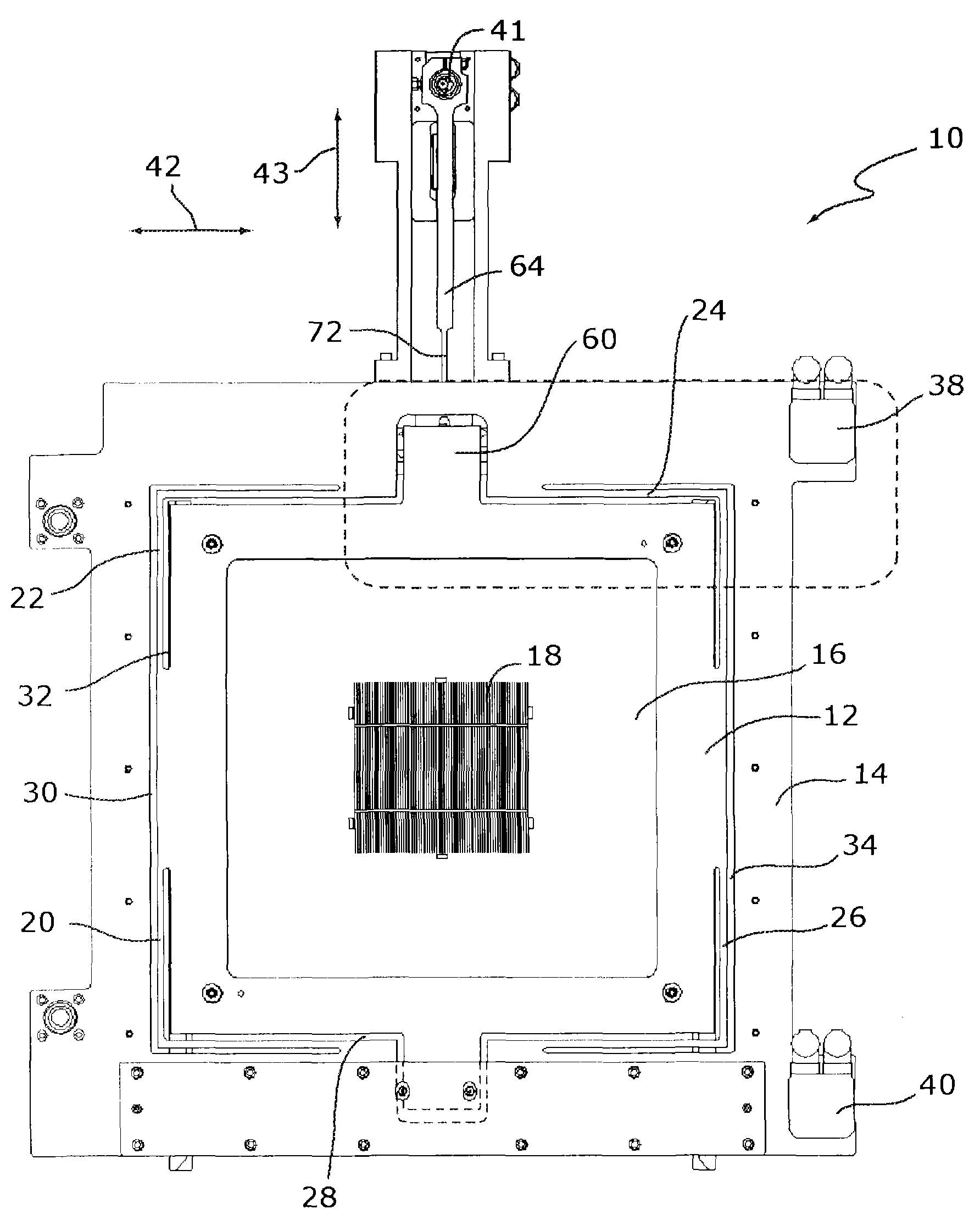
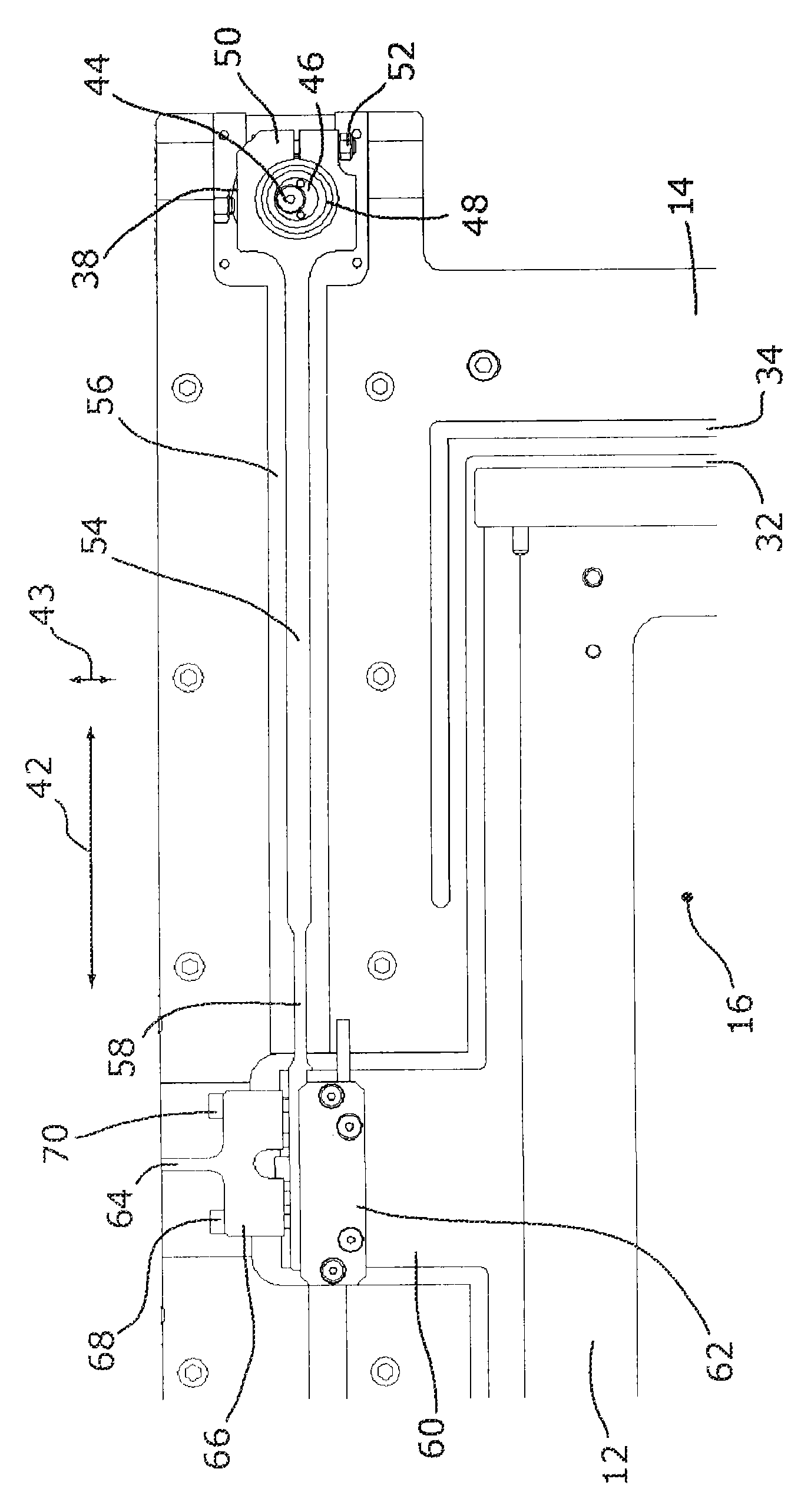
[0024] figure 1A screen positioning device 10 is shown comprising a movable part 12 and a fixed position part 14 . A screen frame is arranged on the movable part 12 for holding a screen 16 with a stencil or printed structure 18 . The movable part 12 is connected to the fixed part 14 by means of flexible parts 20 , 22 , 24 , 26 designed as webs. In this case, the flexible part is produced by introducing openings 28 , 30 , 32 , 34 into metal sheets, in particular aluminum or steel sheets. This measure subdivides the metal plate into a stationary part 14 and a movable part 12 , wherein the parts 12 , 14 are connected by flexible parts 20 , 22 , 24 , 26 . The screen positioning device 10 is thus designed in one piece, ie the position-fixed part 14 and the movable part 12 are connected to one another in a materially bonded manner and formed in one piece. That is, the flexible parts 20 , 22 , 24 , 26 are defined by the material remaining between the movable part 12 and the positi...


PUM


Abstract

The filter positioning arrangement (10) has a mobile unit (12) and a stationary unit (14). A filter (16) is arranged at the mobile unit, which is adjusted over an adjusting unit relative to the stationary unit. A mobile unit is mounted at the stationary unit over flexible elements (20,22,24,26).

Description

technical field [0001] The invention relates to a screen positioning device for positioning a screen (Siebe) in a screen printing unit, which device has at least one movable part and at least one position-fixed part, wherein the screen can be arranged on the movable part, It is adjustable relative to the position-fixed part by means of at least one adjustment mechanism. Background technique [0002] Such a screen positioning device is known, for example, from DE 40 37 678 A1. [0003] When printing substrates using screen printing processes, especially when printing solar cells, functional structures such as surface contacts can be printed. To this end, the substrate is positioned relative to the screen of the screen printing unit. The positioning of the substrate is mostly achieved by adjustable substrate holders. To this end, the substrates must be individually positioned and fixed on adjustable substrate holders. Such positioning of the substrate significantly reduces...

Claims


Application Information

Patent Timeline
Patent Type & Authority Patents(China)
IPC IPC(8): B41F15/14
CPCB41P2215/112B41P2215/50B41F15/36B41F15/08B41F15/14
Inventor D·曼茨A·海姆U·施韦策尔
Owner MANZ AUTOMATION
Learn More