
Overflow device of pulp molding machine

An overflow device and pulp molding technology, applied in textiles and papermaking, etc., can solve the problems of waste of pulp, waste of water, and low control precision, and achieve the effects of improving control precision, saving raw materials and reducing costs.

Inactive Publication Date: 2011-11-16
佛山市昆保达模塑科技有限公司
View PDF7 Cites 3 Cited by
  • Summary
  • Abstract
  • Description
  • Claims
  • Application Information

AI Technical Summary

Problems solved by technology

The traditional overflow process is to store through pipelines, and then use clean water to realize re-grouting. This not only wastes water, but also has low control accuracy and low overflow storage efficiency, which leads to waste of slurry and affects production efficiency.
[0004] There is also an overflow device for pulp molding machines. This device stores the remaining slurry through the cylinder connected to the overflow pipe. When grouting next time, the remaining slurry stored in the cylinder is discharged by controlling the piston in the cylinder. Re-grouting, due to the deposition of the remaining slurry in the storage device of the cylinder, there will be phenomena such as poor dispersion of the remaining slurry and uneven mixing with the new slurry during re-grouting, which will seriously affect the quality of the produced products

Method used


Image

  • Overflow device of pulp molding machine
  • Overflow device of pulp molding machine
  • Overflow device of pulp molding machine

Examples


Embodiment Construction

[0020] In order to better illustrate the purpose, technical solutions and advantages of the present invention, the overflow device of the pulp molding machine of the present invention will be further described below in conjunction with the accompanying drawings and specific examples.

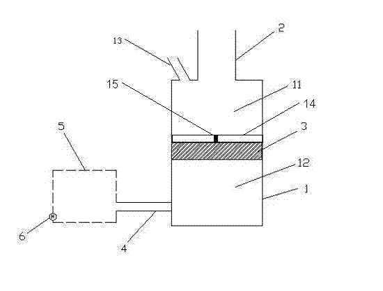
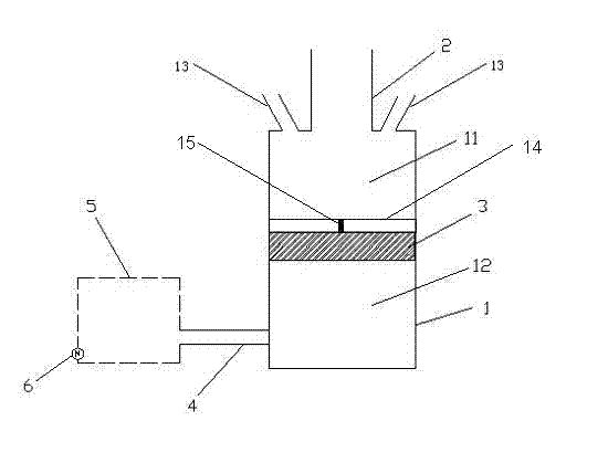
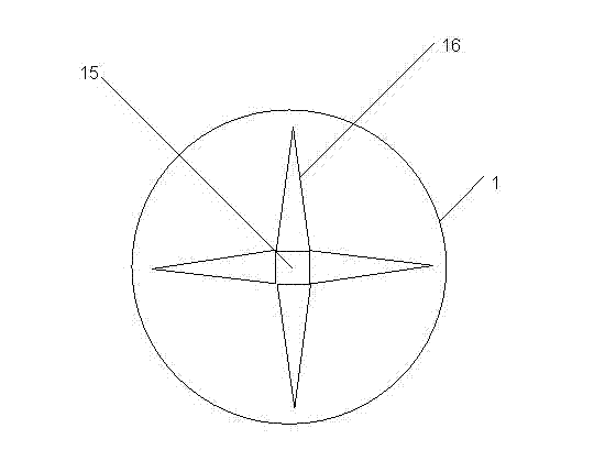
[0021] An embodiment of the present invention is used for the overflow device of the pulp molding machine, as attached figure 1 As shown, the overflow device includes a cylindrical cylinder 1; an overflow pipe 2, one end of the overflow pipe 2 communicates with the cylinder 1; a piston 3, the piston 3 is arranged in the cylinder 1 and the cylinder 1 Divided into a first space 11 and a second space 12 that are sealed and connected, the first space 11 communicates with the overflow pipe 2; a flushing pipe, the flushing pipe is arranged on the side of the overflow pipe and connected to the overflow pipe The cylinder is communicated, and in the present embodiment, a flushing pipe is set on one side ...


PUM


Abstract

The invention provides an overflow device of a pulp molding machine. The overflow device comprises a cylinder, an overflow pipeline, a piston, a slushing pipe, a dispersion stabilization unit, a pneumatic control valve and a synchronous electrical control unit (ECU), wherein, one end of the overflow pipeline is communicated with the cylinder; the piston is arranged in the cylinder and divides the cylinder into a first space and a second space which are hermetically connected together, and the first space is communicated with the overflow pipeline; the slushing pipe is arranged at one side of the overflow pipe and is communicated with the cylinder; the dispersion stabilization unit is arranged in the first space of the cylinder and is connected with the piston, and the dispersion stabilization unit is equipped with a motor for providing power for rotation of the dispersion stabilization unit; the pneumatic control valve is communicated with the second space of the cylinder through a pneumatic control pipeline; and the synchronous ECU is used for controlling on / off of the pneumatic control valve in different directions. The overflow device provided by the invention has the advantages that the residual pulp raw material can be uniformly reused, thus saving raw materials and lowering cost.

Description

technical field [0001] The invention relates to an overflow device of a pulp molding machine, in particular to an overflow device which can evenly recycle the remaining pulp raw materials of the pulp molding machine. Background technique [0002] Pulp molded products are formed in a mold forming machine with a filter screen by adding a certain concentration of pulp and an appropriate amount of chemical additives. In the mold forming machine, the fiber pulp is evenly distributed on the surface of the mold by means of vacuum or pressure, thereby forming a wet paper mold base with the proposed geometry and size, and then undergoes further dehydration, demoulding, drying and finishing, and finally Form a paper product with a specific geometric cavity structure and a certain pressure resistance and cushioning capacity. [0003] The currently used pulp molding machine can automatically complete the process of grouting, suction filtration, cold press setting, heat transfer, drying...

Claims


Application Information

Patent Timeline
Patent Type & Authority Applications(China)
IPC IPC(8): D21J3/00
Inventor 杨仁党韩文佳谭炽东陈克复
Owner 佛山市昆保达模塑科技有限公司
Learn More