Energy-saving electromagnetic clutch

A technology of electromagnetic clutches and stator housings, applied in clutches, magnetic drive clutches, non-mechanical drive clutches, etc., can solve problems such as slow assembly efficiency, achieve volume and weight reduction, reduce the loss of electromagnetic force, and have obvious effects

Active Publication Date: 2012-12-12
成都瑞迪智驱科技股份有限公司
View PDF9 Cites 0 Cited by
  • Summary
  • Abstract
  • Description
  • Claims
  • Application Information

AI Technical Summary

Problems solved by technology

The coil is directly installed in the stator housing and forms a whole with the stator housing by injecting potting material, so the assembly efficiency is relatively slow

Method used


Image

  • Energy-saving electromagnetic clutch
  • Energy-saving electromagnetic clutch
  • Energy-saving electromagnetic clutch

Examples


Embodiment

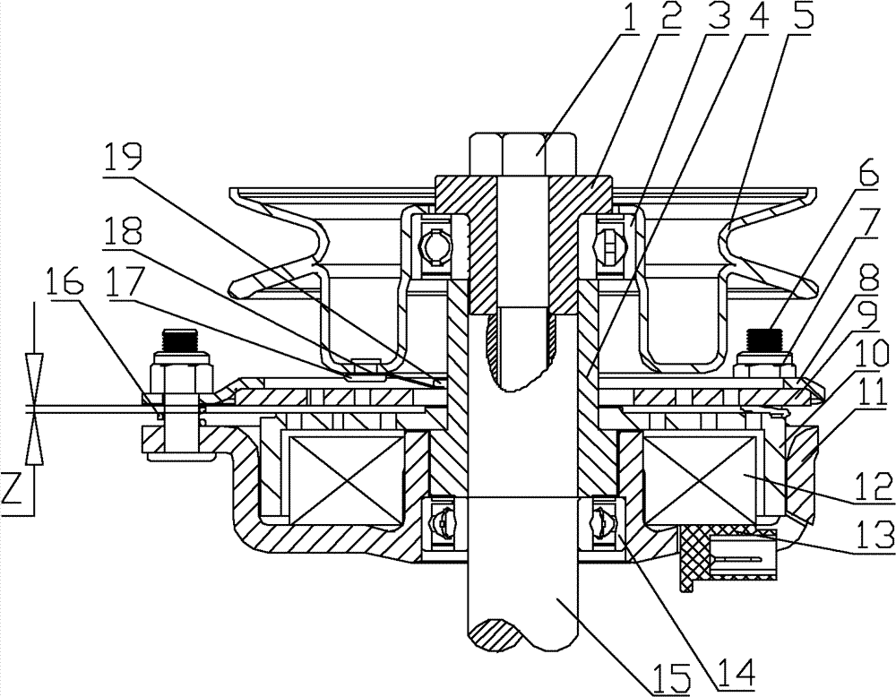
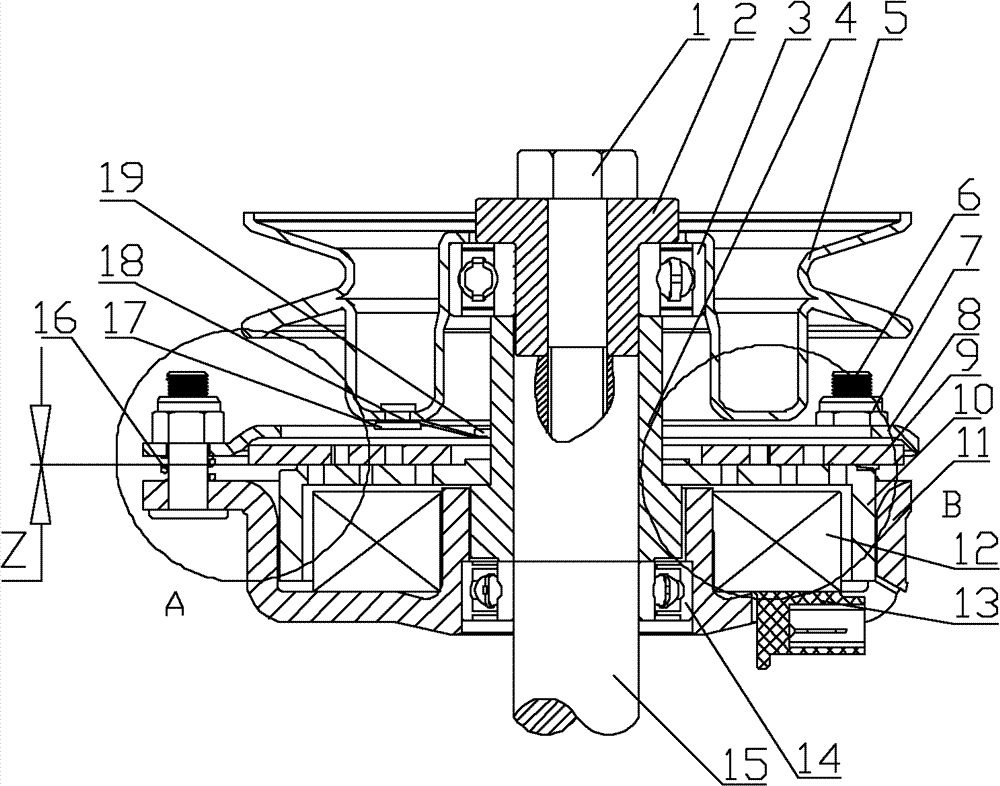
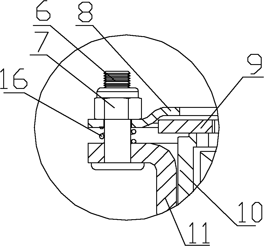
[0027] Such as Figure 1 to Figure 8 As shown, an energy-saving electromagnetic clutch includes a support bolt 6, a tie nut 7, a brake disc cover 8, a leaf spring 18, an armature 9, a rotor 10, and a stator housing 11. The brake disc cover 8 passes through the support bolt 6. The tightening nut 7 is fixed on the stator housing 11, the armature 9 is located between the brake disc cover 8 and the stator housing 11, the brake disc cover 8 and the stator housing A compression spring 16 is provided between the bodies 11, and the compression spring 16 is sleeved on the supporting bolt 6, the rotor 10 is installed in the stator housing 11, and the side wall end surface of the rotor 10 and the stator housing The end surface of the inner side wall of the body 11 is provided with a gap, the stator housing 11 is also provided with a coil 12, the coil 12 is riveted in the stator housing 11, and the end surface of the ring groove of the stator housing 11 is provided with an outward convex ...


PUM


Abstract

The invention discloses an energy-saving electromagnetic clutch, which comprises a carrying bolt, a locking nut, a brake disc cover, an armature, a rotor and a stator shell, wherein the brake disc cover is fixed on the stator shell through the carrying bolt and the locking nut; the armature is positioned between the brake disc cover and the stator shell; a compression spring is arranged between the brake disc cover and the stator shell, and the compression spring is sleeved on the carrying bolt; the rotor is arranged in the stator shell, and a clearance is formed between the end face of the side wall of the rotor and the end face of the inside wall of the stator shell; a coil is arranged in the stator shell, and the coil is riveted in the stator shell; the annular groove end face of the stator shell is provided with an outwards raised lug edge capable of providing an installation position for the clutch and an installation position of the compression spring; and annular strip holes are uniformly distributed on the rotor.

Description

Technical field [0001] The invention relates to an electromagnetic clutch, in particular to an energy-saving electromagnetic clutch. Background technique [0002] The braking function of the electromagnetic clutch in the prior art is realized by the friction between the brake disc cover and the armature, and the structure of the clutch itself determines that the installation of the brake disc cover requires a separate supporting surface to provide a fulcrum for the supporting column. In this way, the solution to the existing electromagnetic clutch is to install the base on the bottom surface of the stator housing. Installing the base separately not only increases the difficulty of assembly, but also directly increases the volume of the electromagnetic clutch itself. This structure also increases the volume of the brake disc cover. The brake disc cover is matched with the base to make the brake The thickness of the moving disc is thick, so that the armature is directly blocked an...

Claims


Application Information

Patent Timeline
Patent Type & Authority Patents(China)
IPC IPC(8): F16D27/08F16D27/14
Inventor 杨凤军丁冬黎启华肖平周小平黄涛廖世全
Owner 成都瑞迪智驱科技股份有限公司
Why Eureka
Try Eureka