Continuous type microwave auxiliary sintering furnace and method

A microwave-assisted, sintering furnace technology, applied in the direction of furnace, electric furnace heating, furnace components, etc., can solve the problems of difficult material heating, difficult microwave, uniformity, etc., to achieve uniform heating, prevent microwave leakage, and uniform particle size distribution

Inactive Publication Date: 2011-11-16
CHENGDU JINGYUAN NEW MATERIALS TECH
View PDF9 Cites 6 Cited by
  • Summary
  • Abstract
  • Description
  • Claims
  • Application Information

AI Technical Summary

Problems solved by technology

This kind of sintering equipment and method has the following disadvantages: (1) the structure of the sintering equipment is difficult to prevent microwave leakage and meets the national safety standards; The structure makes the material to be sintered directly enter the heating box for sintering, and only microwaves are used to heat the sintered material, so it is difficult to heat all parts of the material evenly

Method used


Image

  • Continuous type microwave auxiliary sintering furnace and method
  • Continuous type microwave auxiliary sintering furnace and method
  • Continuous type microwave auxiliary sintering furnace and method

Examples


Embodiment 1

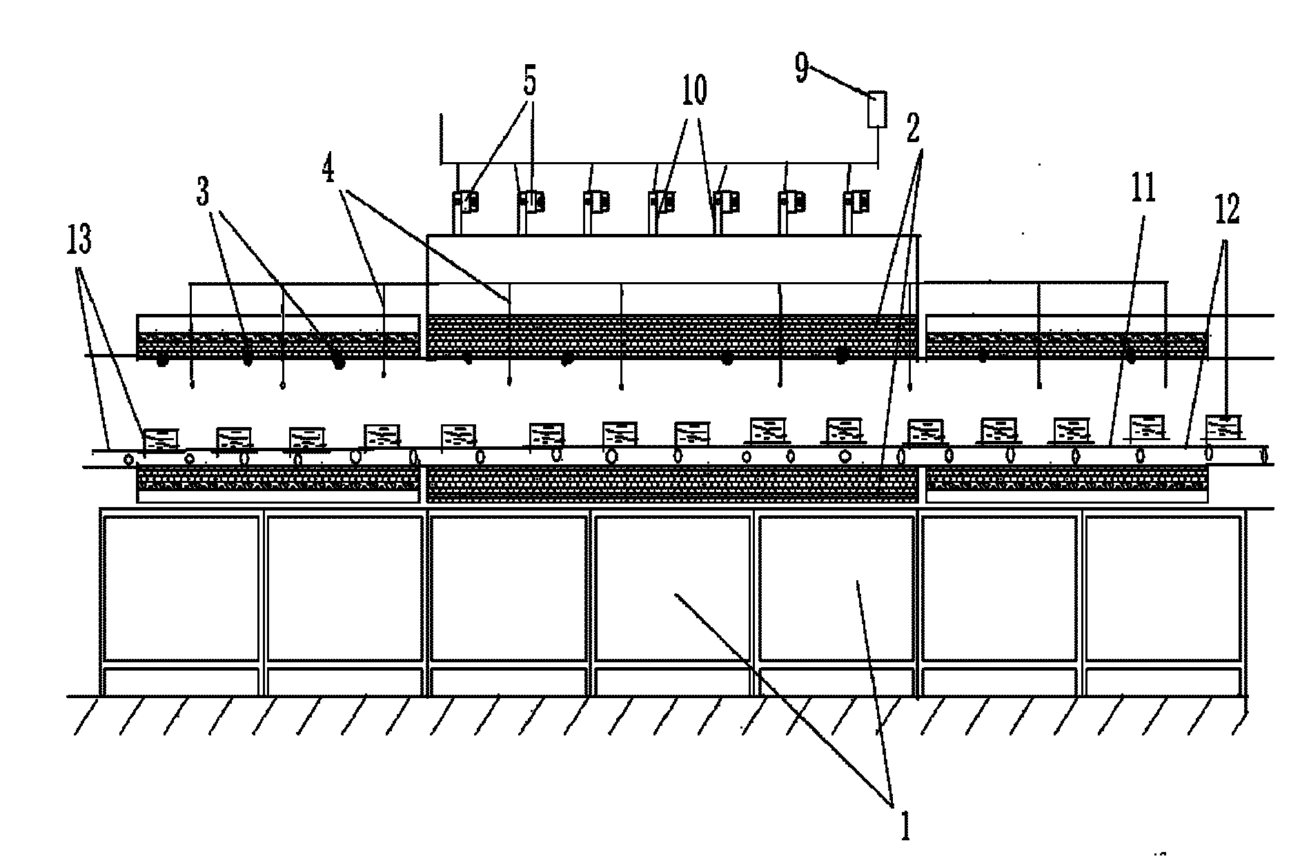
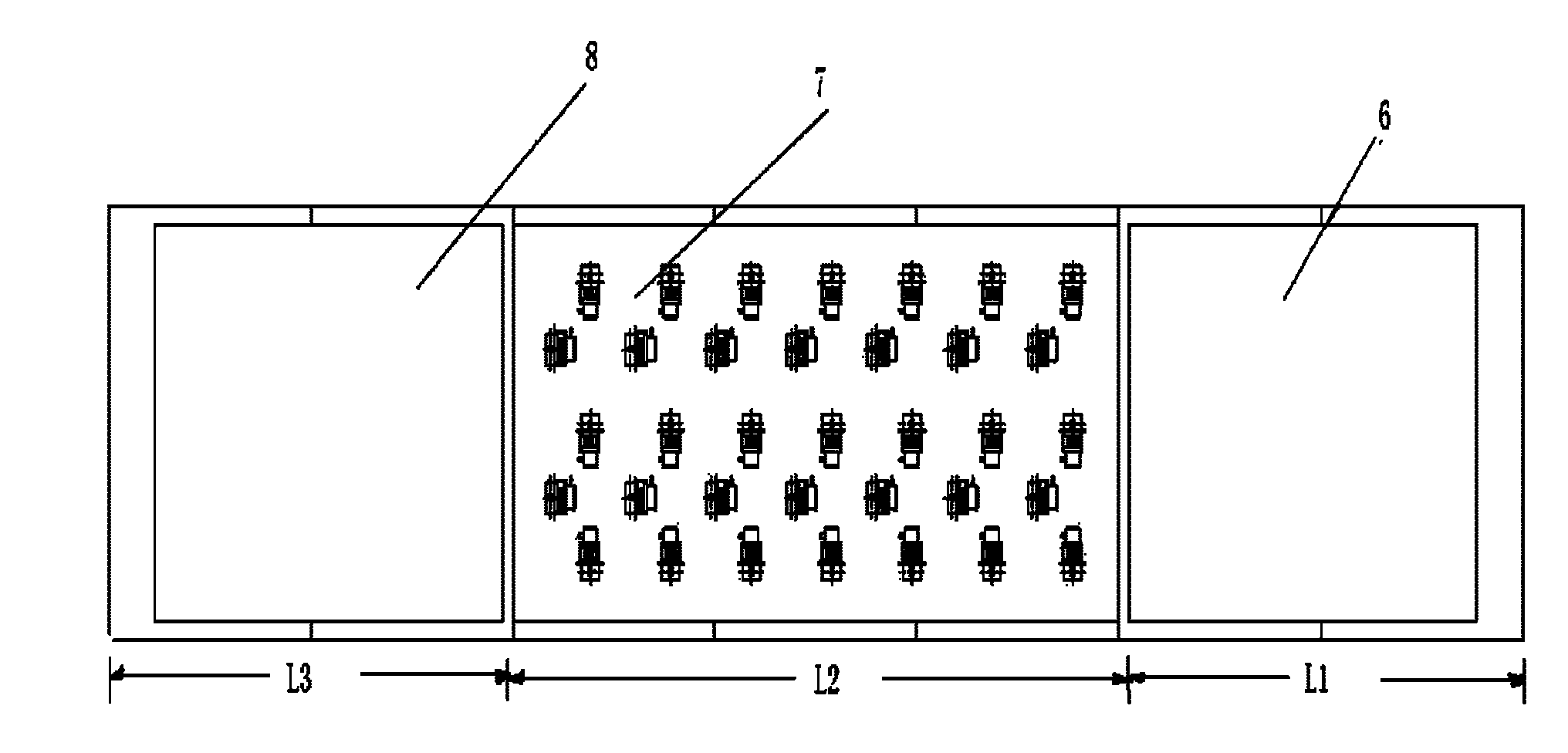
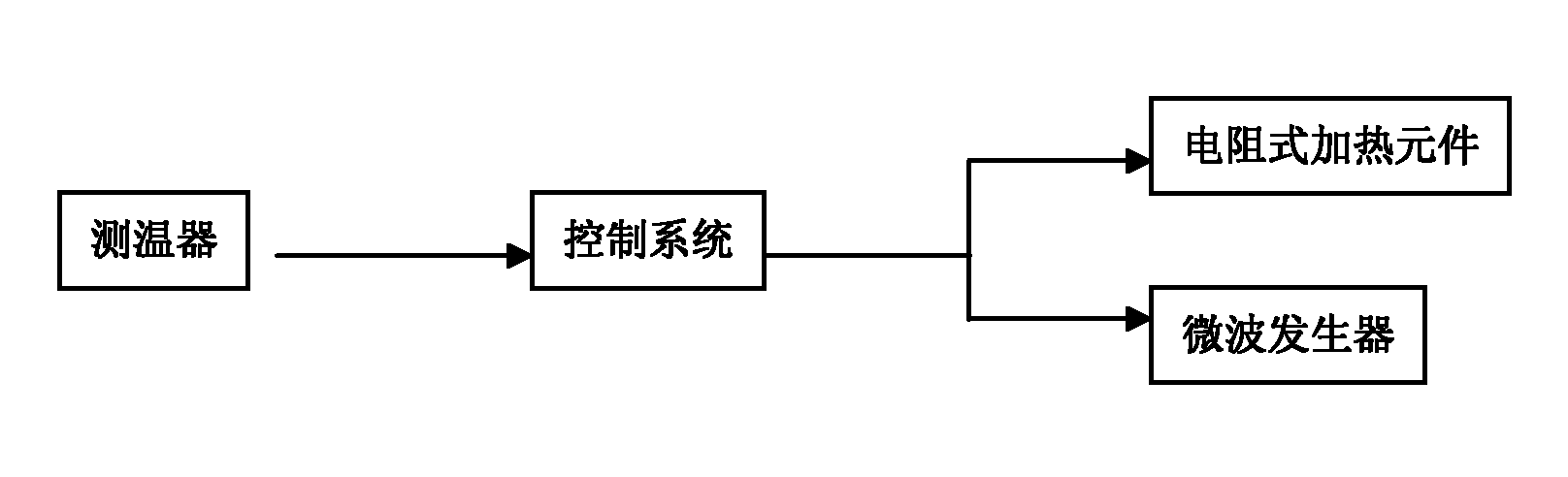
[0034] In this embodiment, the structure of the continuous microwave assisted sintering furnace is as follows figure 1 , figure 2 As shown, it includes a furnace body 1, a thermal insulation layer 2 arranged on the inner wall of the furnace body, a temperature detector 4 arranged in the furnace body, a material transmission device 11 installed in the furnace body, and a water-cooling heat dissipation system 9 arranged outside the furnace body. and control system. The furnace body is a kiln-type structure, which is composed of a first microwave choke section 6, a microwave auxiliary heating section 7 and a second microwave choke section 8 in sequence along the length direction, and the port of the first microwave choke section 6 is sealed and connected There is a feed system 12, and the port of the second microwave choke section 8 is sealed and connected with a discharge system 13; the length L of the first microwave choke section 6 1 = 2L 2 , the length L of the second mic...

Embodiment 2

[0037] In this embodiment, the structure of the continuous microwave assisted sintering furnace is as follows figure 1 , figure 2 As shown, it includes a furnace body 1, a thermal insulation layer 2 arranged on the inner wall of the furnace body, a temperature detector 4 arranged in the furnace body, a material transmission device 11 installed in the furnace body, and a water-cooling heat dissipation system 9 arranged outside the furnace body. and control system. The difference from Example 1 is that the number and arrangement of microwave generators in the microwave-assisted heating section of the furnace body are determined according to the microwave power density gradient in the furnace chamber of the microwave-assisted heating section. Such as Figure 4 As shown, the length L of the middle section 14 of the microwave-assisted heating section of the furnace body 4 =1 / 2L 2 , the length L from the left end of the middle section of the microwave-assisted heating section t...

Embodiment 3

[0039] This embodiment uses the continuous microwave assisted sintering furnace with the structure described in Example 1, and the length L of the microwave assisted heating section 7 2 =10.8 meters, the length L of the first microwave choke section 6 1 =21.6 meters, the length L of the second microwave choke section 8 3 =10.8 meters, adopt the sintering method of the present invention to sinter battery cathode material LiNi 1 / 3 co 1 / 3 mn 1 / 3 o 2 , the operation steps are as follows:

[0040] (1) Drying and heating of the furnace body

[0041] Turn on the power, operate the control system, start the resistance heating elements of the first microwave choke section, the microwave auxiliary heating section and the second microwave choke section, and heat the furnace body of each section to 200°C at a heating rate of 5°C / hour Keep warm for 8 hours, dry the furnace body; then raise the temperature of the microwave auxiliary heating section to 880°C at a heating rate of 10°C / h...


PUM

PropertyMeasurementUnit
particle sizeaaaaaaaaaa

Abstract

The invention relates to a continuous type microwave auxiliary sintering furnace which comprises a furnace body, a temperature detector arranged in the furnace body, a material transmission device installed in the furnace body, a water-cooling heat-removal system and a control system, wherein the water-cooling heat-removal system and the control system are arranged outside the furnace body; the furnace body is successively composed of a first microwave choke section, a microwave auxiliary heating section and a second microwave choke section, resistance-type heating elements are installed in the furnace body walls of the first microwave choke section and the second microwave choke section, a resistance-type heating element is installed in the furnace body wall of the microwave auxiliary heating section, and microwave generators are installed on the exteriors of the furnace body walls. The invention discloses a continuous type microwave auxiliary sintering method which comprises the following steps: drying the furnace body of each section by virtue of electrical heating, and heating the microwave auxiliary heating section until the temperature is below 50-100 DEG C required for sintering a sintered material; carrying out microwave heating and the electrical heating until the temperature of the microwave auxiliary heating section is increased to the temperature required for sintering the sintered material and keeping the temperature constant; and then sintering the material.

Description

technical field [0001] The invention belongs to the field of material sintering, in particular to a continuous microwave-assisted heating sintering furnace and a sintering method for solid materials such as battery cathode materials and ceramic materials. Background technique [0002] The sintering process is an important link in the synthesis of battery cathode materials and ceramic materials. During the sintering process, the material forms unique physical and chemical characteristics such as crystal structure, particle size, morphology, dislocations, and defects, so that the material has unique properties. At present, the sintering equipment used at home and abroad are mainly resistance heating sintering furnaces and small-scale intermittent microwave sintering furnaces used in laboratories. [0003] The traditional resistance heating sintering is an external heating method, that is, the resistance heating element first heats the furnace body to the sintering temperature...

Claims


Application Information

Patent Timeline
Patent Type & Authority Applications(China)
IPC IPC(8): F27D11/00F27B9/36
Inventor 徐频陈东州
Owner CHENGDU JINGYUAN NEW MATERIALS TECH
Why Eureka
Try Eureka