
Interpolation type device for measuring resistance of superconducting joint

A technology for measuring superconducting joints and resistance, which is applied to measuring devices, measuring magnetic variables, and measuring electrical variables, etc. It can solve the problems of cumbersome measurement process and sample replacement, high volatilization rate of liquid helium, and increased cost of superconducting joint resistance testing.

Inactive Publication Date: 2011-11-16
INST OF ELECTRICAL ENG CHINESE ACAD OF SCI
View PDF3 Cites 4 Cited by
  • Summary
  • Abstract
  • Description
  • Claims
  • Application Information

AI Technical Summary

Problems solved by technology

Therefore, the traditional superconducting joint resistance measurement device must have a set of low-temperature Dewar, and the sample with superconducting joint, superconducting transformer, and back field magnet are all placed in the liquid helium tank in the low-temperature Dewar for cooling, and the liquid helium tank is cooled outside the liquid helium tank. There are also cold screen system and vacuum Dewar system, which make the structure of this superconducting joint resistance measurement device complex, and the measurement process and sample replacement are also quite cumbersome.
In addition, it usually takes several days to measure a superconducting joint sample, and the traditional superconducting joint resistance measurement device has a high volatilization rate of liquid helium, which greatly increases the testing cost of superconducting joint resistance

Method used


Image

  • Interpolation type device for measuring resistance of superconducting joint
  • Interpolation type device for measuring resistance of superconducting joint
  • Interpolation type device for measuring resistance of superconducting joint

Examples


Embodiment Construction

[0022] The present invention will be further described below in conjunction with the accompanying drawings and specific embodiments.

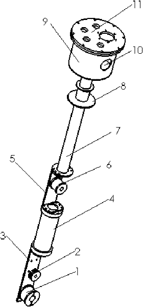
[0023] Such as figure 1 As shown, the present invention mainly includes two parts, the sample room inside the tank and the operating area outside the tank, and these two parts are connected by a metal pipe 7 . The sample chamber in the tank is located at the lower end of the metal tube 7 , and the operating area outside the tank is located at the upper end of the metal tube 7 .

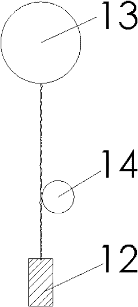
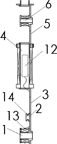
[0024] Such as figure 1 with image 3 As shown, the sample chamber in the tank of the present invention is mainly composed of a superconducting transformer 1, a magnetic field measuring seat 2, a back field superconducting magnet 4, etc., these components are arranged side by side along the axial direction, and the superconducting transformer 1 is sequentially arranged from bottom to top . The magnetic field measuring seat 2 and the back field superconducting magnet...


PUM


Abstract

The invention discloses an interpolation type device for measuring the resistance of a superconducting joint. The device comprises two parts, namely an in-tank sample chamber and an out-tank operating area, wherein the in-tank sample chamber consists of a superconducting transformer (1), a magnetic-field measuring seat (2) and a back-field superconducting magnet (4); during measurement, the superconducting joint (12) is placed in an inner hole of the back-field superconducting magnet (4), and the back-field superconducting magnet (4) generates a background magnetic field; a single-turn sensing ring (13) of a superconducting joint sample is sleeved on outer layers of coils of the superconducting transformer (1), and the superconducting transformer (1) senses a current in the superconducting joint sample; a single-turn measuring ring (14) of the superconducting joint sample is embedded in a middle groove of the magnetic-field measuring seat (2); a magnetic-field measurement probe which is arranged in a central hole of the magnetic-field measuring seat (2) measures the size of a central magnetic field of the single-turn measuring ring (14) of the superconducting joint and calculates the current in the superconducting joint sample; and during operation, the in-tank sample chamber is completely inserted into a liquid helium storage tank (15) and soaked and cooled in liquid helium.

Description

technical field [0001] The invention relates to a device for measuring the resistance of a superconducting joint between coils of a superconducting magnet. Background technique [0002] Superconducting magnets, especially large and medium-sized superconducting magnets, are generally composed of many superconducting coils connected in series. Due to the limitation of the length of commercially supplied superconducting wires or the different requirements of superconducting coils on superconducting wire parameters and the needs of magnet winding process, it is impossible for each superconducting coil in a superconducting magnet to be wound with the same superconducting wire. Superconducting wires must be welded with resistance or superconductivity, and the quality of the joints between these superconducting wires will directly affect the stable operation of the superconducting magnet system. In some superconducting application fields, such as nuclear magnetic resonance imaging...

Claims


Application Information

Patent Timeline
IPC IPC(8): G01R27/02G01R33/07H01F6/00H01F36/00
CPCY02E40/66Y02E40/60
Inventor 陈顺中王秋良程军胜
Owner INST OF ELECTRICAL ENG CHINESE ACAD OF SCI
Learn More