High-speed neutron photographing device

A camera device, neutron technology, applied in high-speed photography, focusing device, photography, etc., can solve the problem of difficult to meet the field of view range and resolution requirements, and achieve automatic adjustment measurement, ideal shielding effect, and simplify the shielding structure. Effect

Active Publication Date: 2011-11-16
CHINA INSTITUTE OF ATOMIC ENERGY
View PDF9 Cites 3 Cited by
  • Summary
  • Abstract
  • Description
  • Claims
  • Application Information

AI Technical Summary

Problems solved by technology

[0004] The two existing neutron high-speed camera devices in the world both use a structure with a fixed distance between the CMOS camera and the scintillation screen. The advantages are simple structure, easy shielding, and convenient operation. The disadvantage is that it is difficult to meet different field of view and resolution requirements.

Method used


Image

  • High-speed neutron photographing device
  • High-speed neutron photographing device
  • High-speed neutron photographing device

Examples


Embodiment Construction

[0016] The present invention will be described in detail below in conjunction with the accompanying drawings and embodiments.

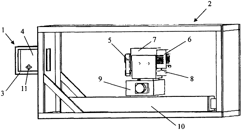
[0017] Such as figure 1 As shown, the high-speed neutron imaging device includes two parts: a neutron conversion cavity 1 and a detection cavity 2 . The neutron conversion cavity 1 converts neutron images into visible light images, and the detection cavity 2 is used to collect light signals. The frame material of the two cavities is made of aluminum alloy profiles with a cross-section of 2cm*2cm, and the outer skin is clad with 2mm thick aluminum foil. The cavities are connected by 4 screws. In this embodiment, the frame volume of the neutron conversion cavity is 40cm*40cm*40cm, and the frame volume of the detection cavity is 60cm*80cm*120cm.

[0018] The neutron conversion chamber 1 is provided with a scintillation screen 3 for converting neutron images into visible light images, and a plane mirror 4 is provided behind the scintillation screen 3 f...


PUM


Abstract

The invention relates to a neutron imaging technology, in particular to a high-speed neutron photographing device which structurally comprises a neutron conversion cavity and a detection cavity, wherein the neutron conversion cavity is provided with a scintillation screen for converting a neutron image into a visible image, and a plane mirror for refracting visible light to the detection cavity is arranged at the rear side of the scintillation screen; the detection cavity is internally provided with a lens and a high-speed CMOS (Complementary Metal-Oxide-Semiconductor Transistor) camera; the lens and the high-speed CMOS camera are wholly arranged in a shielding lead box, the lens faces to a visible light incident direction, and a translation platform capable of driving the lens and the high-speed CMOS camera to move wholly is arranged in the detection cavity. The high-speed neutron photographing device provided by the invention can respond to different view field ranges and resolution requirements and can be used for performing automatic focusing on different object distances so as to guarantee automatic regulation and measurement of online belts.

Description

technical field [0001] The invention relates to neutron imaging technology, in particular to a high-speed neutron imaging device. Background technique [0002] Neutron imaging works on the same principle as X-ray fluoroscopy, except that neutrons are used to penetrate objects. Compared with X-ray imaging, neutron imaging has stronger penetrating power and can see lighter elements, such as C, H, O, N, etc. The disadvantage is that the neutron imaging intensity is weak, so the resolution and noise are worse than X-rays. [0003] At present, there are mainly three types of neutron sources used in neutron imaging, which are isotopic neutron sources (neutron flux at the measured object ~10 3 n / cm 2 / s), accelerator neutron source (neutron flux at the measured object ~ 10 3 n / cm 2 / s to 10 6 n / cm 2 / s), and the reactor neutron source (neutron flux at the measured object ~ 10 5 n / cm 2 / s to 10 9 n / cm 2 / s). The strongest neutron source is the reactor, so only the neutro...

Claims


Application Information

Patent Timeline
Patent Type & Authority Applications(China)
IPC IPC(8): G03B39/00G03B13/18
Inventor 贺林峰韩松柏王洪立郝丽杰武梅梅王雨魏国海陈东风刘蕴韬吴立齐
Owner CHINA INSTITUTE OF ATOMIC ENERGY
Why Eureka
Try Eureka