Pipe having grooved inner surface, apparatus for producing the same and method for producing the same

A manufacturing method and a manufacturing device technology, applied to the field of pipes with grooves on the inner surface, can solve problems such as inability to process, and achieve the effect of light weight

Inactive Publication Date: 2011-11-16
FURUKAWA ELECTRIC CO LTD
View PDF8 Cites 9 Cited by
  • Summary
  • Abstract
  • Description
  • Claims
  • Application Information

AI Technical Summary

Problems solved by technology

[0016] However, even if the overall tensile load can be reduced, when the tensile load changes, it cannot be processed completely corresponding to this load change.
[0017] For example, in the manufacturing device disclosed in Patent Document 6, an intermediate drawing device is configured, and a wiper is provided to prevent the gasket in contact with the substrate from sliding relative to the substrate, and the groove shape of the gasket is specified, but the load variation still remains will happen

Method used


Image

  • Pipe having grooved inner surface, apparatus for producing the same and method for producing the same
  • Pipe having grooved inner surface, apparatus for producing the same and method for producing the same
  • Pipe having grooved inner surface, apparatus for producing the same and method for producing the same

Examples


Embodiment 1

[0161] Embodiment 1 of the present invention is jointly described in conjunction with the following drawings.

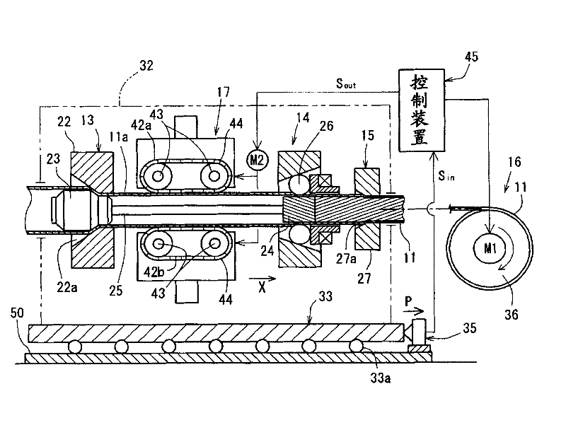
[0162] The manufacturing method of the inner surface grooved pipe 11 in the present embodiment can use figure 1 The production apparatus 12 shown performs the production.

[0163] in addition, figure 1 It is an explanatory drawing of the manufacturing apparatus 12 of the inner surface grooved pipe in this Example.

[0164] The manufacturing device 12 is drawn from the drawing direction (stretching direction) ( figure 1 In the X direction) the upstream side to the downstream side is sequentially arranged to reduce the diameter part 13, the auxiliary drawing device 17, the groove processing part 14, and the trimming processing part 15, and the drawing device 16 is included on the further downstream side, and these configurations are continuous The inner surface grooved tube 11 is manufactured by processing the base tube 11a.

[0165] In detail, the manufacturing de...

Embodiment 2

[0256] Next, the manufacturing apparatus 101 and the manufacturing method of the inner grooved pipe of Example 2 will be described.

[0257] The manufacturing apparatus 101 of inner surface grooved pipe is arranged in this order from the upstream side with the diameter reduction device 120 for reducing the diameter of the base pipe 201 as the processing object 200, and the groove processing for performing groove processing on the inner surface of the reduced diameter pipe 202 after diameter reduction. Apparatus 140, and reel 160 of inner surface grooved tube 204 after drawing groove processing.

[0258] In addition, a conveyance assisting device 130 that assists in conveying the reduced diameter tube 202 in the conveyance direction of the groove processing device 140 is provided between the diameter reducing device 120 and the groove processing device 140 .

[0259] In addition, on the inner surface grooved pipe manufacturing device 101, the fixed diameter reducing device 120 ...

Embodiment 9

[0266] An embodiment of the present invention will be described together with the following drawings.

[0267] Figure 4 It is a configuration diagram showing an inner grooved tube manufacturing apparatus 101 of the second embodiment. Should Figure 4 A device for processing, a device for sensing, and a device for control are shown in . in addition, Figure 5 It is an explanatory diagram for explaining the load applied to the raw material, the drawing force for processing, the auxiliary conveying force, and the detected load in the inner grooved pipe manufacturing apparatus 101 .

[0268] When describing the processing device, from upstream to downstream, the respective processing parts of the diameter reducing device 120, the auxiliary conveying device 130, the groove processing device 140, and the finishing processing device 150 are arranged horizontally and in a straight line, and in the downstream A reel 160 that draws and winds the base pipe 201 in a straight line is ...


PUM


Abstract

Provided is a pipe having a grooved inner surface, which has excellent thermal conduction properties, can be made compact and lightweight, and allows resources to be conserved. Also provided are a method and apparatus for producing this pipe having a grooved inner surface, which allow efficient and stable production thereof. The apparatus which is used for producing the pipe having a grooved inner surface is provided with: diameter-reducing means for drawing a base pipe in order to reduce the diameter thereof, and groove-forming means for forming a large number of grooves on the inner surface of the base pipe. If, for example, the angle of twist of a groove with respect to the centre axis of the pipe is beta (DEG) and the apex angle of a fin which is formed between adjacent grooves is alpha (DEG), then beta is between 30 and 60 and alpha is between 5 and 20. If the outer diameter is D (mm), the groove depth is H (mm), and the cross-sectional area with respect to the axial direction of the pipe is Ac (mm<2>), then D is no greater than 6, H is at least 0.07, and Ac is less than 0.8*D.

Description

technical field [0001] The present invention relates to an inner surface grooved tube used as a heat transfer tube for heat exchangers such as refrigerators and air conditioners, and a method for manufacturing the same. Background technique [0002] Heat transfer tubes used in heat exchangers of heat pump equipment such as air conditioners and water heaters are often grooved on the inner surface in order to improve heat exchange performance, such as copper inner surface grooved tubes. [0003] In recent years, in order to respond to the miniaturization and high efficiency of heat exchangers, the grooves formed on the inner surface have been deepened, the helix angle (lead angle) of the grooves has been increased, the fins have become sharper, and the wall thickness of the tubes has been increased. Thinned inner surface grooved tubes to improve heat exchanger performance. [0004] For example, in the following patent document 1, a small-diameter heat transfer tube with an ou...

Claims


Application Information

Patent Timeline
Patent Type & Authority Applications(China)
IPC IPC(8): B21C1/22B21C3/16
CPCB21C37/207B21C1/30B21C1/27B21C1/20B21C1/24B21C3/16B21C3/08B21C1/22B21D53/06F28F1/40
Inventor 田口忠尹荣德钓弘太郎桥爪利明正武家和昭
Owner FURUKAWA ELECTRIC CO LTD
Why Eureka
Try Eureka