Turbulent-flow crushing machine of soybean milk maker

The technology of a pulverizing device and a soymilk machine is applied to beverage preparation devices, milk substitutes, household appliances, etc., which can solve the problems of prolonged pulverization time, shutdown of the soymilk machine, poor defoaming effect, etc., so as to reduce the pulverization time and improve the defoaming effect. , the effect of improving the effect

Inactive Publication Date: 2011-11-23
MIDEA GRP CO LTD
View PDF3 Cites 11 Cited by
  • Summary
  • Abstract
  • Description
  • Claims
  • Application Information

AI Technical Summary

Problems solved by technology

However, this netless soymilk machine needs to set spoiler ribs on the wall of the cup to enhance the effect of spoiling and crushing, which makes the structure of the cup wall more complex and unsightly
Chinese patent 200120142987.6 discloses a multifunctional soymilk machine, which sets the turbulence structure (that is, the turbulence surface body) above the crushing cutter instead of on the cup wall, which solves the problem of the beauty of the cup body to a certain extent , but because the turbulent curved surface body is set above the crushing tool, that is, the crushing tool is lower than the lower end surface of the turbulent curved surface body, so th

Method used


Image

  • Turbulent-flow crushing machine of soybean milk maker
  • Turbulent-flow crushing machine of soybean milk maker
  • Turbulent-flow crushing machine of soybean milk maker

Examples


Example Embodiment

[0025] Example 2:

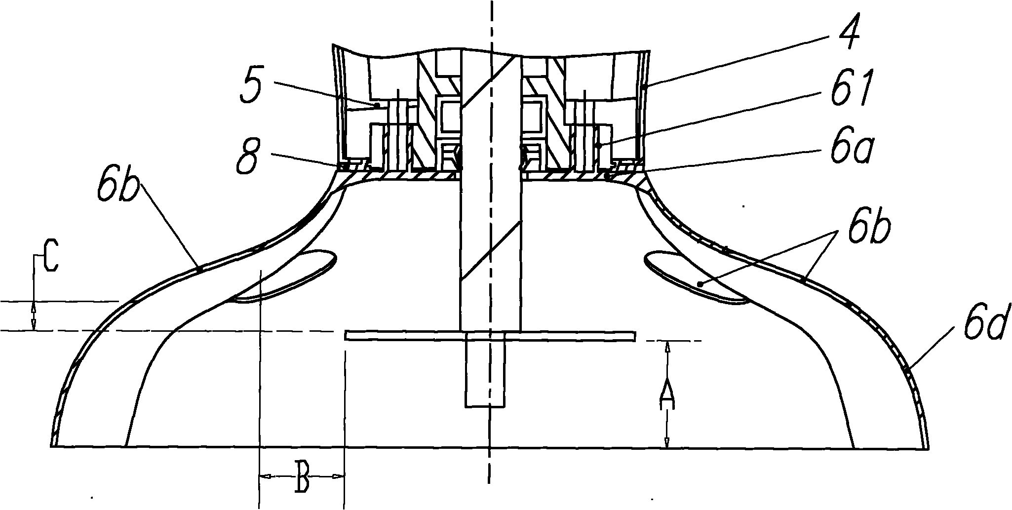
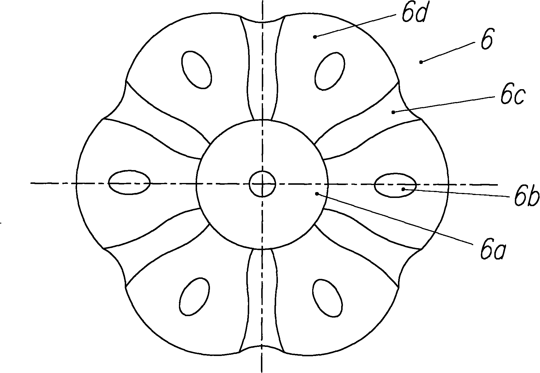
[0026] Such as Figure 4 As shown, the difference between this embodiment and Embodiment 1 is that the bottom surface of the spoiler cover 6 is provided with regularly distributed concave units 6e. The concave unit 6e provided on the bottom surface can also play a role in enhancing the turbulence effect.

Example Embodiment

[0027] Example 3:

[0028] Such as Figure 4 As shown, the difference between this embodiment and the first embodiment is that the spoiler assembly is a spoiler cover-shaped body composed of a plurality of spoilers 6f welded or fixedly connected to a fixing plate 6a. Similarly, each spoiler 6f is provided with a convex unit 6d. This kind of spoiler cover-shaped body composed of the spoiler 6f, due to the gap between the adjacent spoilers, this gap acts as a spoiler Because of the role of the hole, there is no need to specifically provide a spoiler hole on the spoiler 6f.

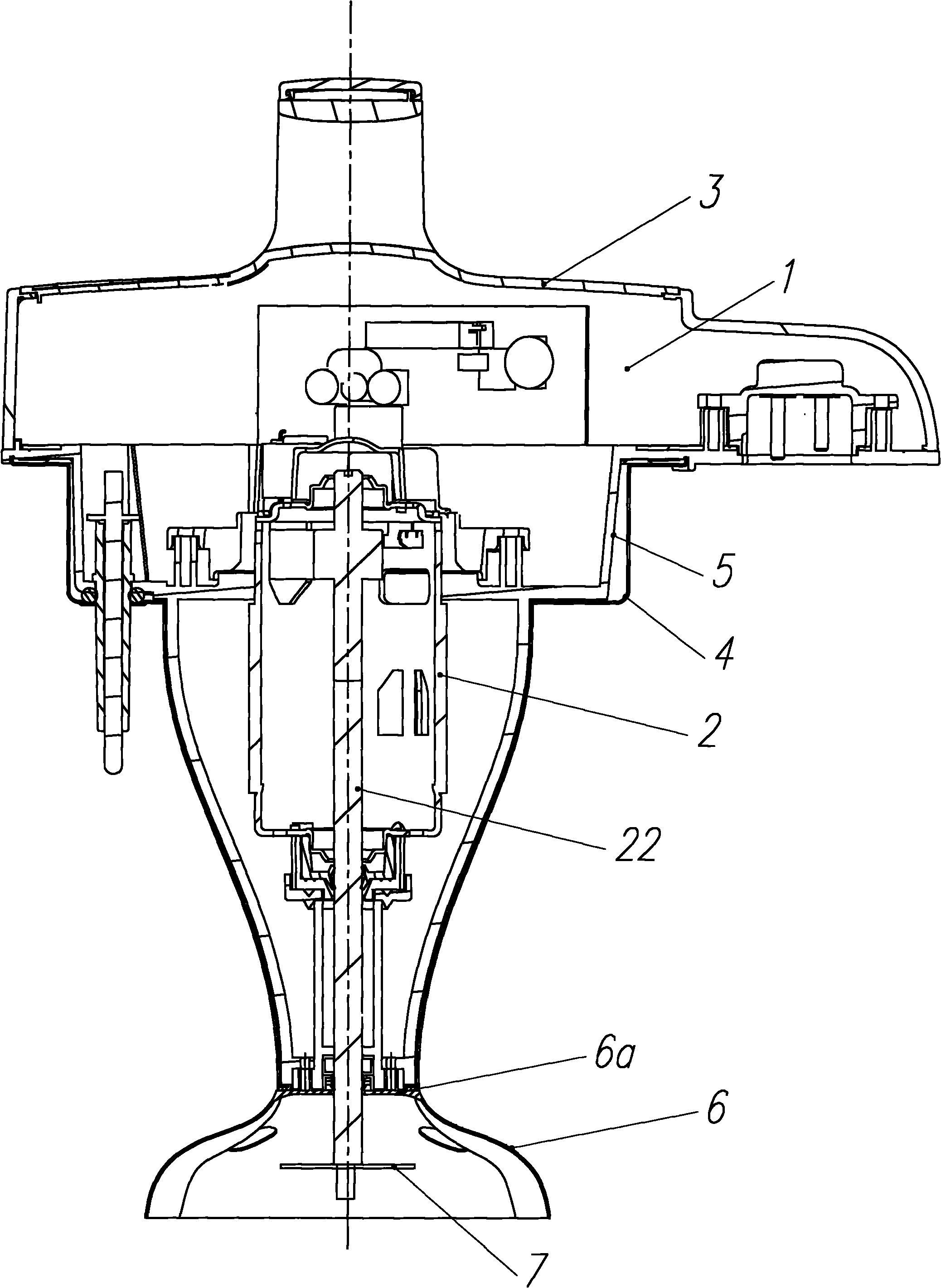
[0029] At the same time, in all the above embodiments, the spoiler components are directly connected to the lower head cover 4 respectively, but may also be indirectly connected to the lower head cover 4 through an intermediate component.


PUM

PropertyMeasurementUnit
The maximum diameteraaaaaaaaaa

Abstract

The invention discloses a turbulent-flow crushing machine of a soybean milk maker, which comprises a machine head, a motor arranged in the machine head, a curved-surface body turbulent-flow component and a crushing and pulping tool connected with the motor through a shaft and is characterized in that: the turbulent-flow component is directly or indirectly mounted on the machine head; the turbulent-flow component is an integrated turbulent-flow cover or a turbulent-flow cover-like body consisting a plurality of turbulent-flow plates; a space for accommodating the shaft passing through is preserved in the center of the turbulent-flow component; and the lower end face of the crushing and pulping tool is not lower than the lower end face of the turbulent-flow component. In the invention, by arranging the curved-surface body turbulent-flow component and mounting the crushing and pulping tool at a position on the same height as or on a lower height than the lower end face of the turbulent-flow component, the problem that turbulent and crushing actions are independent of each other and cannot promote each other in the prior art is solved. The design allows a high negative pressure is formed on the periphery of the crushing and pulping tool, so the flowing of the pulp is accelerated; therefore, the crushing effect is improved, crushing time is reduced and a good defoaming effect is achieved.

Description

technical field [0001] The invention relates to the field of soymilk makers and belongs to the modification technology of the existing soymilk makers. Background technique [0002] The pulverizing device of existing soya-bean milk machine is generally installed on the machine head of soya-bean milk machine, is divided into fine-mesh soya-bean milk machine, large-network (usually called Lafar net) soya-bean milk machine and non-mesh soya-bean milk machine by the difference of pulverizing system. Fine meshes have the disadvantage of being difficult to clean. The Lafar net soymilk machine solves the problem of difficult cleaning to a certain extent, and the non-mesh soymilk machine completely solves the problem of difficult cleaning. Therefore, the non-mesh soymilk machine has been recognized by the market and loved by consumers. However, this non-net soymilk machine needs to arrange spoiler ribs on the wall of the cup body to enhance the effect of spoiling and crushing, which...

Claims


Application Information

Patent Timeline
IPC IPC(8): A47J31/44A23C11/10A23L11/60
Inventor 吴明川李前荣王小霞
Owner MIDEA GRP CO LTD
Why Eureka
Try Eureka