Ultrasonic diagnostic apparatus, ultrasonic image processing apparatus, and medical diagnostic imaging apparatus

A technology of image processing device and diagnostic device, which is applied in sonic diagnosis, ultrasonic/sonic/infrasonic diagnosis, infrasonic diagnosis, etc., to achieve the effect of simple visual recognition

Active Publication Date: 2011-11-23
TOSHIBA MEDICAL SYST CORP
View PDF10 Cites 6 Cited by
  • Summary
  • Abstract
  • Description
  • Claims
  • Application Information

AI Technical Summary

Problems solved by technology

[0010] On the other hand, the animation observation of dynamic information may not be called objective due to the need to remember the time changes of each position in the mind
In addition, there is also a problem that observation takes a certain amount of time

Method used


Image

  • Ultrasonic diagnostic apparatus, ultrasonic image processing apparatus, and medical diagnostic imaging apparatus
  • Ultrasonic diagnostic apparatus, ultrasonic image processing apparatus, and medical diagnostic imaging apparatus
  • Ultrasonic diagnostic apparatus, ultrasonic image processing apparatus, and medical diagnostic imaging apparatus

Examples


Deformed example 1

[0111] In the present four-dimensional parametric imaging, in the projection processing of step S6, the thickness (projection range) of data in the depth direction to be the object of the projection processing can be adjusted. For example, a desired tomographic image is displayed according to a user's instruction. The image generation unit 25 considers a predetermined range centered on the tomographic image displayed in the depth direction, a predetermined range from the displayed tomographic image to the rear side of the screen, and a predetermined range from the displayed tomographic image to the front side of the screen. Specify the thickness (projection range) in the depth direction based on the displayed tomographic image. In addition, the projection range can be adjusted arbitrarily according to manual operation by an operator.

[0112] With such a configuration, if the projection range can be set, the user can set the observation range very easily, and it can be improv...

Embodiment 2

[0114] In the present four-dimensional parametric imaging, in the projection processing in step S6, it is possible to select (change / adjust) the voxel to be the projection processing target based on the contrast agent information. For example, by performing threshold processing on the second volume data, it is also possible to selectively display voxels that are earlier or later in the time information of the contrast agent. For example, a predetermined threshold may be set for the contrast agent time information according to an instruction from the user, unnecessary voxels may be excluded by threshold processing using the threshold, and the second volume data may be projected and displayed.

Deformed example 3

[0116] In this four-dimensional parametric imaging, in the projection processing of step S6, it is also possible to cover the thickness of the data in the depth direction (projection range) that is the target of the projection processing within the entire range of the first, second, and third volume data. .

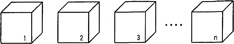
[0117] For example, if Figure 12 As shown, in the depth direction, the first, second, and third volume data are equally divided into sub-volume data Vs1-Vsn, and the projection processing in step S6 is performed using each sub-volume data as a projection range. The division width of the sub-volume data can be arbitrarily set by an operator's manual operation.

[0118] Additionally, if Figure 13 As shown, the first, second, and third volume data are divided into sub-volume data Vs1 to Vsn each having an arbitrary width in the depth direction, and the projection processing of step S6 is performed using each sub-volume data as a projection range. The width of each subvo...


PUM


Abstract

According to one embodiment, there is provided an ultrasonic diagnostic apparatus includes a data acquisition unit configured to scan a three-dimensional region in a subject having a contrast agent injected therein over a predetermined period by using ultrasonic waves and to thereby acquire ultrasonic data concerning the three-dimensional region over the predetermined period, a volume data generation unit; configured to generate first volume data in each time phase in an analysis period by using the ultrasonic data concerning the three-dimensional region over the analysis period in the predetermined period and to generate second volume data indicative of contrast agent temporal information about the analysis period and third volume data indicative of a contrast agent characteristic amount at each position in the three-dimensional region in the analysis period, and an image generation unit configured to generate a projected image by using the second volume data and the third volume data.

Description

[0001] Cross References to Related Applications [0002] This application is based on and claims priority from prior Japanese Patent Application No. 2010-078909 filed on March 30, 2010, the entire contents of which are hereby incorporated by reference. technical field [0003] The embodiments described herein generally relate to ultrasonic diagnostic devices, ultrasonic image processing devices, and medical image diagnostic devices. Background technique [0004] The present invention relates to an ultrasonic diagnostic device and the like capable of three-dimensionally visualizing temporal changes in blood flow dynamics in organs and the like to be image-diagnosed by using microbubbles as an ultrasonic contrast agent, and relates to an ultrasonic diagnostic device capable of high visual recognition. Ultrasonic diagnostic equipment, ultrasonic image processing equipment, and medical image diagnostic equipment that can easily observe information such as dynamic blood flow chan...

Claims


Application Information

Patent Timeline
Patent Type & Authority Applications(China)
IPC IPC(8): A61B8/06A61B8/00
CPCG01S15/8979A61B8/463A61B8/483G01S15/8993A61B8/481G01S7/52071A61B8/461A61B8/466
Inventor 吉田哲也久我衣津纪
Owner TOSHIBA MEDICAL SYST CORP
Why Eureka
Try Eureka