Correction method and correction apparatus for laser marking and laser marking system

A laser marking and calibration method technology, applied in the optical field, can solve the problems of low accuracy, the calibration accuracy cannot meet the high-precision requirements, and can not meet the industry requirements, and achieves the effect of high calibration accuracy.

Active Publication Date: 2013-07-03
SHENZHEN TETELASER TECH CO LTD
View PDF7 Cites 1 Cited by
  • Summary
  • Abstract
  • Description
  • Claims
  • Application Information

AI Technical Summary

Problems solved by technology

[0004] But in fact, due to the existence of errors in optical devices and electromechanical devices, when the marking range is large, various errors are combined and amplified, resulting in correction accuracy that cannot meet certain high-precision requirements
In addition, the traditional correction formula is a linear correction, but in reality, the accuracy of different areas is different at the same distance from the center of the mark. Some areas have high precision, and some areas have low precision. Therefore, using a linear correction formula will also cause deviations.
[0005] The above reasons cause the traditional calibration method to have a large error and fail to meet the requirements of processing accuracy. Generally, in the commonly used processing area of ​​100mm*100mm, the maximum error can reach 0.5mm, which cannot meet the industry requirements. For example, the semiconductor industry often requires processing. Accuracy reaches 0.01~0.03mm

Method used


Image

  • Correction method and correction apparatus for laser marking and laser marking system
  • Correction method and correction apparatus for laser marking and laser marking system
  • Correction method and correction apparatus for laser marking and laser marking system

Examples


Embodiment Construction

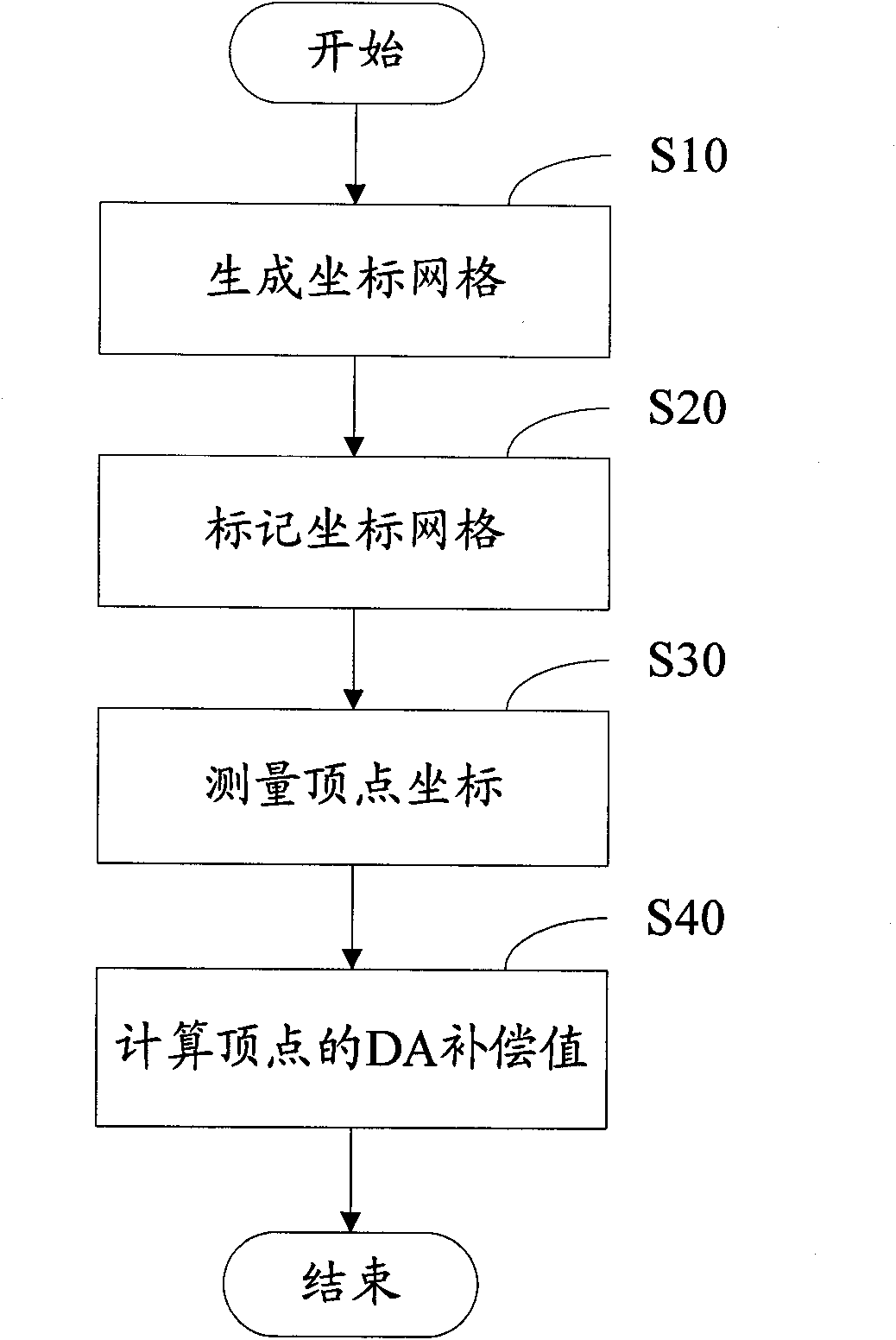
[0041] The correction method for laser marking of the present invention firstly needs to obtain error data. Such as figure 2 As shown, in a preferred embodiment, the error data can be obtained through the following steps:

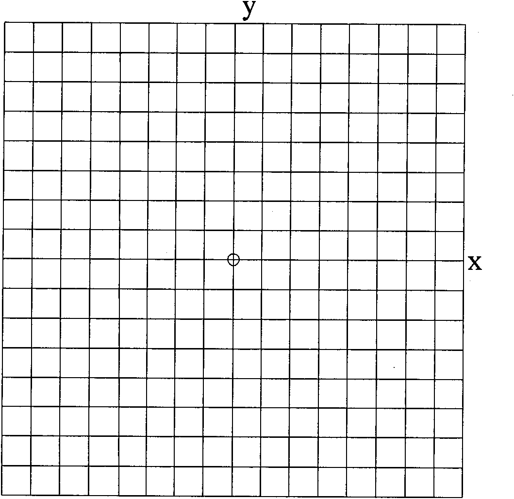
[0042] S10, generating a coordinate grid.

[0043] Divide the area to be marked (such as a 100mm*100mm square) into 2 k line 2 k Column grid coordinate grid (k is a positive integer), the size of k can be selected according to the calibration accuracy, the larger k is, the higher the calibration accuracy is, but at the same time, the time required for calibration will increase geometrically. In a preferred embodiment, N is 16, 32 or 64 (ie k=4, 5, 6), image 3 It is a grid diagram of grid coordinates when N=16 in one embodiment.

[0044] S20, mark the coordinate grid.

[0045] Use the laser marking system to be calibrated to mark the grid map of the grid coordinates on the horizontal calibration plate.

[0046] S30, measure the coordinates of the ve...


PUM


Abstract

The invention relates to a correction method for laser marking, which comprises the following steps: calculating the position information of each point in a graph to be marked; calculating the DA correction value of each point in the graph to be marked; correcting according to the DA Values ​​are corrected for each point. The invention also relates to a laser marking correction device and a laser marking system. The laser marking system using the above correction method realizes high-precision laser marking. No matter where the errors of the optical and electrical systems of the marking machine come from, the errors of the limited points are used in the correction process, and the errors of the infinite points are introduced and corrected. , with high calibration accuracy. When the coordinate grid is 64 rows and 64 columns, it can achieve a marking accuracy of 0.01mm level, which basically meets the current marking accuracy requirements of all industries.

Description

【Technical field】 [0001] The present invention relates to the field of optics, in particular to a calibration method for laser marking, a calibration device for laser marking, and a laser marking system. 【Background technique】 [0002] The galvanometer scanning laser marking system guides the high-energy laser beam to the processed product for marking through optical refraction, reflection and focusing. Due to the characteristics of the optical lens group, the focal plane of the laser will appear spherical and pincushion distortion. Such as figure 1 Shown is the distorted figure when a square figure is actually marked. [0003] The traditional correction method is mainly through the analysis of pure optical and electromechanical system principles, such as the analysis of light refraction characteristics, reflection characteristics, focusing characteristics, galvanometer deflection, transmission system, analog-to-digital conversion and other errors, so as to derive a set of...

Claims


Application Information

Patent Timeline
Patent Type & Authority Patents(China)
IPC IPC(8): B41J29/393
Inventor 何德乐盛辉吴华安蔡桓欧景华
Owner SHENZHEN TETELASER TECH CO LTD
Why Eureka
Try Eureka