
Flow path switching valve

A flow channel switching and valve casing technology, which is applied in the field of flow channel switching valves, can solve problems such as difficulties and achieve the effects of preventing creep deformation, reliable moving action, and preventing stress deformation

Active Publication Date: 2011-11-23
SAGINOMIYA SEISAKUSHO INC
View PDF8 Cites 8 Cited by
  • Summary
  • Abstract
  • Description
  • Claims
  • Application Information

AI Technical Summary

Problems solved by technology

Therefore, it is difficult for the main valve chamber and the auxiliary valve chamber to achieve pressure equalization smoothly, and there is still room for improvement.

Method used


Image

  • Flow path switching valve
  • Flow path switching valve
  • Flow path switching valve

Examples


Embodiment Construction

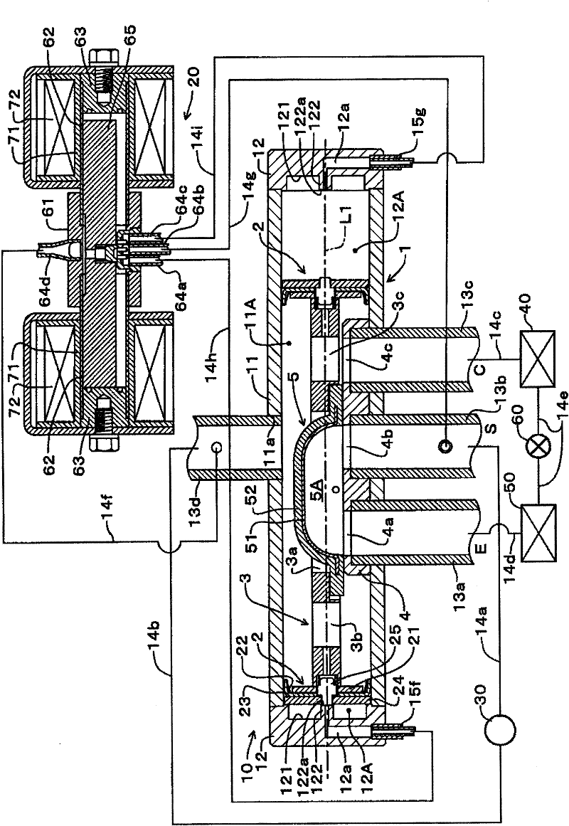
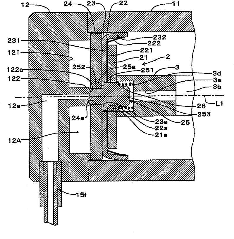
[0022] Next, embodiments of the present invention will be described. figure 1 It is a figure which shows the channel switching valve, control valve, and refrigeration cycle of embodiment. The channel switching valve 10 of this embodiment is a four-way switching valve, and the channel switching valve 10 is connected to the control valve 20 by piping. In the channel switching valve 10 , the valve housing 1 has a cylindrical shape and is composed of a cylindrical portion 11 of a cylindrical shape and two cover portions 12 , 12 of a disc shape. The caps 12, 12 are mounted on the cylindrical portion 11 by welding to close the ends of the cylindrical portion 11 respectively. A thin circular concave portion 121 is formed on the cylindrical portion 11 side of the cover portion 12, 12.

[0023] Two pistons 2 , 2 arranged on an axis L1 of the valve housing 1 and connected to each other by a connecting member 3 are housed in the valve housing 1 . Thus, the inside of the valve case 1, ...


PUM


Abstract

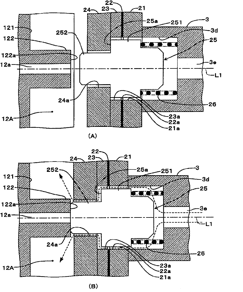
The invention relates to a flow path switching valve. The flow path switching valve 10 uses two pistons 2, 2 to divide a valve shell 1 into a primary valve chamber 11A and the secondary valve chambers 12A, 12A on two sides. One secondary valve chamber 12A on one side is decompressed and a pressure difference between this secondary valve chamber and a refrigerant pressure in the primary valve chamber 11A is used to drive the piston 2 and a primary valve core 5 to move, convert the flow path of the refrigerant in circulation and guarantee the service durability of the piston 2. A pressure equalizing path is provided in the center of the piston 2, and a secondary valve 25 is disposed in the pressure equalizing path. When the piston 2 is moved toward a cap 12, the secondary valve 25 closes anopening of an exhaust path 12a at a secondary valve seat, and opens the pressure equalizing path.

Description

technical field [0001] The present invention relates to a channel switching valve used in refrigeration cycles of air conditioners and the like to switch refrigerant channels. Background technique [0002] Conventionally, in an air conditioner or the like, the cooling operation and the heating operation can be switched by switching the flow path of the refrigerant in the refrigeration cycle. In this refrigerating cycle, a compressor, two heat exchangers used as a condenser or an evaporator, and a channel switching valve for switching a channel of refrigerant flow between these compressors and the two heat exchangers are used. [0003] As such a channel switching valve, there is, for example, the technique disclosed in JP-A-2009-68695 (Patent Document 1). The channel switching valve accommodates a piston body in which two pistons and a main valve core are connected in a cylindrical valve case (valve body), and makes the main valve body slide in the axial direction relative t...

Claims


Application Information

Patent Timeline
Patent Type & Authority Applications(China)
IPC IPC(8): F16K11/065F16K31/122
CPCF25B41/046F25B41/26
Inventor 村田雅弘
Owner SAGINOMIYA SEISAKUSHO INC
Learn More