
Hybrid permanent anchor

a permanent anchor and hybrid technology, applied in the field of hybrid permanent anchors, can solve the problems of large load reduction, small load reduction due to creep, and difficulty in ensuring a predetermined level of anchoring force, so as to prevent creep (deformation), and reduce the divergence angle of force

Active Publication Date: 2021-11-11
DONG A SPECIAL CONSTR CO LTD +2
View PDF5 Cites 0 Cited by
  • Summary
  • Abstract
  • Description
  • Claims
  • Application Information

AI Technical Summary

Benefits of technology

The present disclosure aims to solve problems in the related art by providing a hybrid permanent anchor with several technical effects. The first technical effect is to have a tension part, fixed body, compression body, PC steel strand, and anchor head, which allows for balancing loads and reducing concentrated-load. The second technical effect is to distribute and reduce concentrated-load using the advantages of tension and compression types. The third technical effect is to reduce force divergence angle by dividing a concentrated load in both sides (up and down). The fourth technical effect is to prevent creep (deformation) by restrictions pressure due to long-term tension at the boundary between a fixed body and tension compression part. The fifth technical effect is to increase stability by reducing the outer diameter and length of the anchor so that the effect of keeping it fixed is increased. The sixth technical effect is to prevent breakage for a long period of time by distributing loads at a lower fixed part when the anchor is tensed. The seventh technical effect is to be able to manufacture a product that decreases load and increases anchoring force when using FRP resin with low compression and large tension and being advantageous for attaching to the tension part of the fixed body. The eighth technical effect is to prevent breakage between concrete and the anchor. The ninth technical effect is to prevent breakage of concrete at the boundary between a tension type and a compression type. The eleventh technical effect is to remarkably improve the quality and reliability of a permanent anchor.

Problems solved by technology

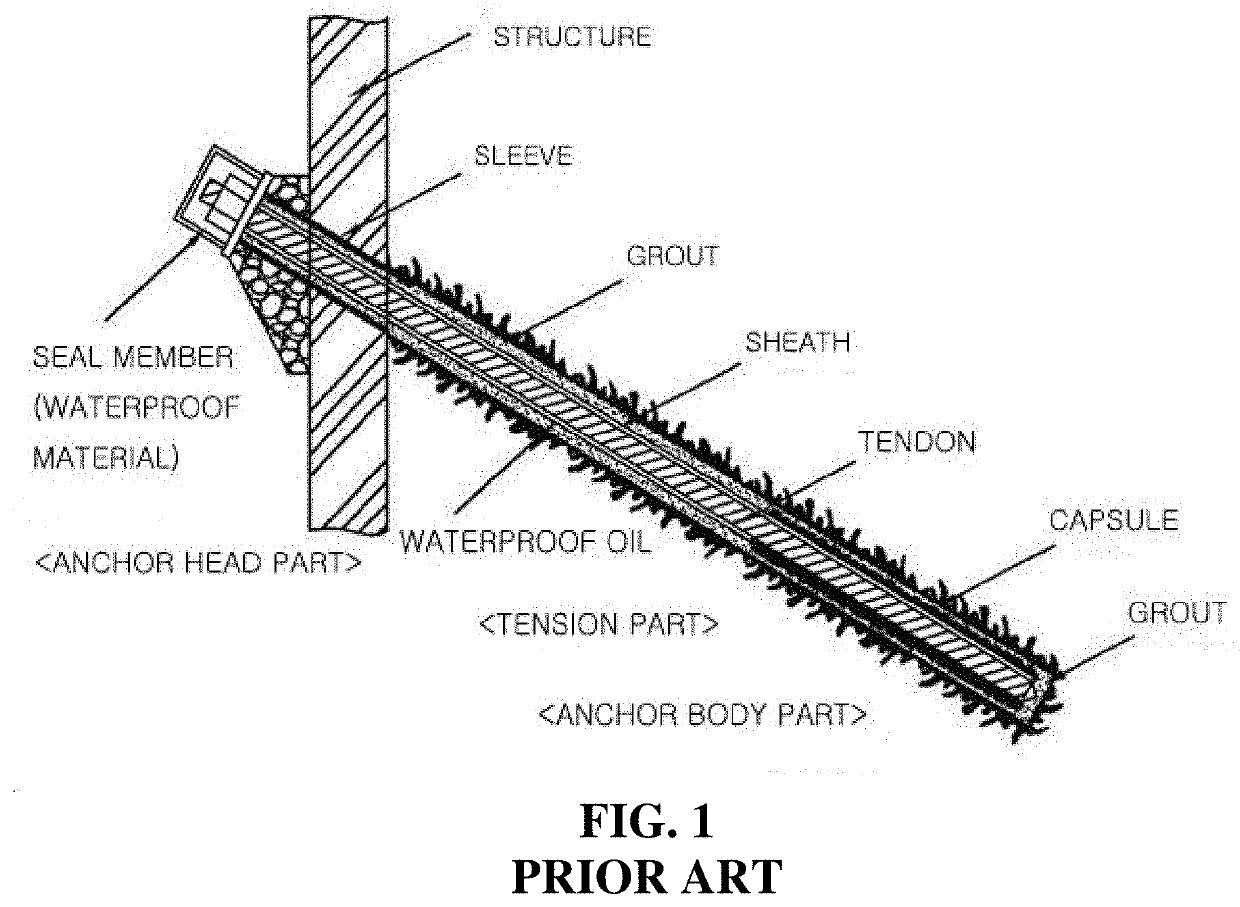
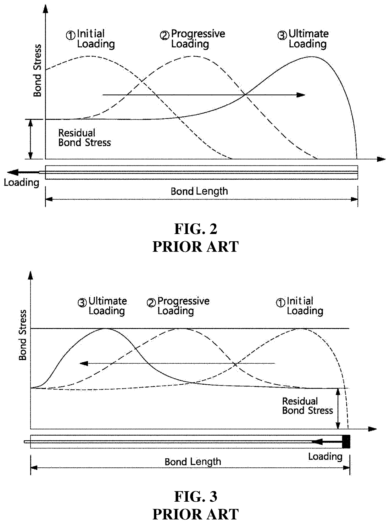
Such a tension anchor is widely used inside and outside the country as a most common anchor, and has an advantage that there are sufficient study results and actual construction results, but has a fault that progressive failure is generated by tensile cracks in grout and creep due to load concentration, so load reduction is large.
The compression anchor has a fault that load reduction due to creep is small in comparison to the tension anchor, but high-strength grout is required and it is difficult to secure a predetermined level of anchoring force in a relatively weak ground.
That is, since tension anchors of the related art are tension types, creep (deformation) is generated by long-period tension, the outer diameter increases, and there is no effect at the boundary of a free length and a fixed part, that is, large problems were found.
Further, the compression anchors of the related art are broken when they are used for a long period of time due to a concentrated load at the lower fixed part when the free length is tensed and breakage is frequently generated between concrete and the anchors, that is, large problems were generated.
There is a structure obtained by mixing the tension type and the compression type to solve the problems in the related art, but a problem was found that concrete frequently breaks at the boundary between the tension type and the compression type.
The following prior art documents have been disclosed to solve the problems in the related art, but a problem that it is difficult to solve all of the problems in the related art was found.

Method used


Image

  • Hybrid permanent anchor
  • Hybrid permanent anchor
  • Hybrid permanent anchor

Examples


first embodiment

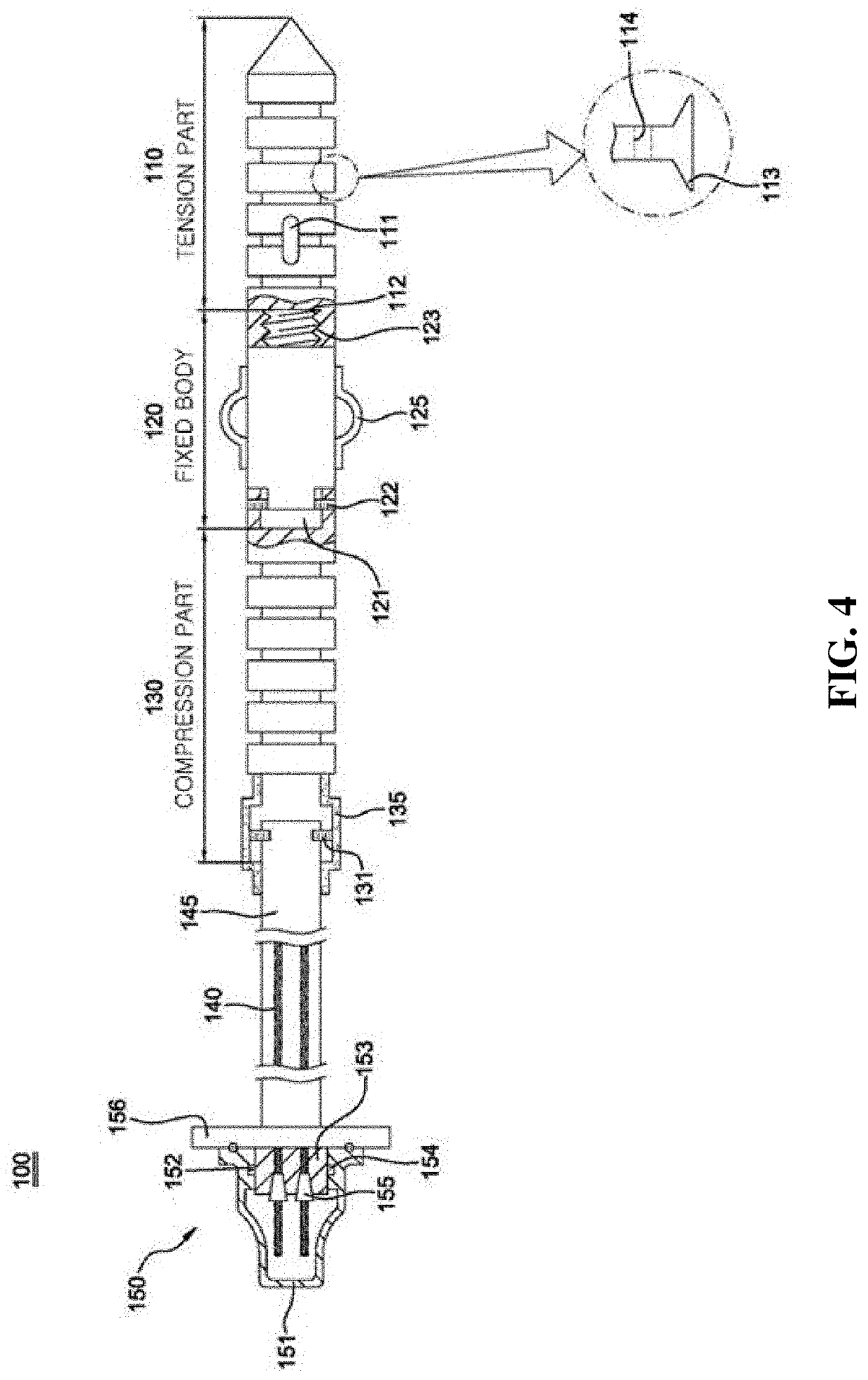
[0073]To this end, FIG. 4 shows the configuration of the hybrid permanent anchor 100 of the present disclosure.

[0074]The present disclosure has the tension part 110 and the compression part 130 at both sides of the fixed part 120, and the pipe 145 having the PC steel strands 140 therein and the anchor head part 150 are sequentially connected to the compression part 130.

[0075]The assembly of the permanent anchor 100 of the present disclosure is installed by inserting the permanent anchor 10 into a hole formed in a slope, injecting grout into the hole, installing a lattice block, tensing the permanent anchor 100, and then coupling the anchor cap 151 of the anchor head part 150.

[0076]According to the present disclosure, the fastening hole 112 of the tension part 110 is fastened to the bolt 123 at the front end of the fixed body 120 and the set screw 122 is fastened to the locking portion 121 at the rear end of the fixed body 120, whereby the tension part 110 and the compression part 13...

second embodiment

[0082]FIG. 5 shows the configuration of the hybrid permanent anchor 100 of the present disclosure.

[0083]The second embodiment of the present disclosure is the same as the first embodiment except for the configuration and operation effects of the tension part 110a, so only these are described hereafter.

[0084]That is, according to the second embodiment of the present disclosure, the fastening hole 112a of the tension part 110a is fastened to the bolt 123 at the front end of the fixed body 120 and the set screw 122 is fastened to the locking portion 121 at the rear end of the fixed body 120, whereby the tension part 110a and the compression part 130 are coupled with the fixed body 120 therebetween.

[0085]In particular, according to the present disclosure, the wires 113a are connected to the tension wedge 114a between the first tension body 111a and the second tension body 116a and the coil 115a is fitted in the locking grooves 117a formed on the outer surfaces of the first tension body ...


PUM


Abstract

A hybrid permanent anchor is proposed. The hybrid permanent anchor includes: a fixed body disposed between a compression part and a tension part and coupling the compression part and the tension part to each other; the tension part coupled to a front end of the fixed body and transmitting tension to the permanent anchor when tensile stress is generated; the compression part coupled to a rear end of the fixed body and transmitting compressive force to the permanent anchor when compressive stress is generated; a PC steel strand coupled to a rear end of the compression part and having a protective pipe thereon; and an anchor head part fixing the permanent anchor to a structure.

Description

CROSS REFERENCE TO RELATED APPLICATION[0001]This application claims priority to and the benefit of Korean Patent Application No. 10-2020-0054701, filed on May 7, 2020, the disclosure of which is incorporated herein by reference in its entirety.BACKGROUND OF THE INVENTIONTechnical Field[0002]An embodiment of the present disclosure relates to a hybrid permanent anchor and, more particularly, to distribute and reduce a concentrated-load generated in a permanent anchor to ¼ using only the advantages of a tension type and a compression type to be advantageous in terms of maintaining force for a long period of time, thereby considerably improving the quality and reliability of the permanent anchor to give a good image.Description of the Related Art[0003]It should be noted that the present disclosure has been improved from previously registered patents by the applicant(s).[0004]As well known, an anchor is a device that transmits load from a structure to the ground by tensioning a tension m...

Claims


Application Information

Patent Timeline
IPC IPC(8): E02D5/80
CPCE02D5/808E02D2600/30E02D2300/0051E02D2300/0034E02D5/805E02D29/0233E02D5/76E02D5/801E02D2600/20
Inventor SIM, SUCK RAELEE, NAN HEE
Owner DONG A SPECIAL CONSTR CO LTD
Learn More