Fuel cell system and fuel cell module thereof

A fuel cell system and fuel cell technology, applied in the direction of fuel cells, fuel cell additives, fuel cell grouping, etc., can solve problems such as poor contact of electrodes or other components, poor overall performance of fuel cells, etc.

Inactive Publication Date: 2011-11-23
IND TECH RES INST
View PDF3 Cites 0 Cited by
  • Summary
  • Abstract
  • Description
  • Claims
  • Application Information

AI Technical Summary

Problems solved by technology

[0004] Conventional fuel cells in some cases have poor contact between electrodes or other components due to insufficient contact force between internal components, which will lead to poor overall performance of the fuel cell

Method used


Image

  • Fuel cell system and fuel cell module thereof
  • Fuel cell system and fuel cell module thereof
  • Fuel cell system and fuel cell module thereof

Examples


Embodiment Construction

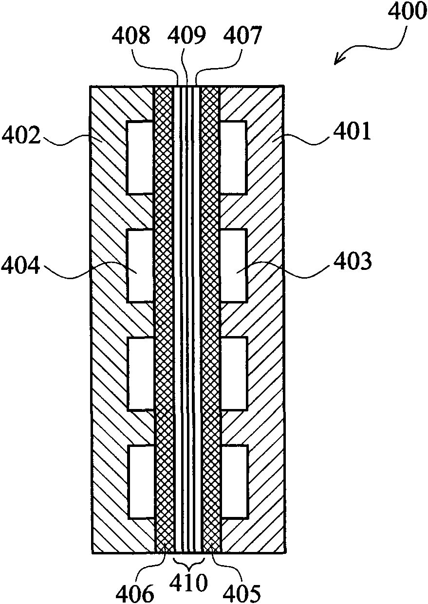
[0050] An embodiment of the present invention provides a fuel cell module, wherein non-planar structures are formed on one or more components inside the fuel cell module, so that a contact force can be generated during or after the fuel cell module is assembled. In one embodiment, an arc-shaped or polygonal structure protruding toward the membrane electrode group can be formed on the collector element or other elements. With the cooperation of system design, practical application or other factors, the aforementioned contact force can indeed strengthen the inter-element contact force. Conductivity, uniformity of conduction and / or reliability under long-term use.

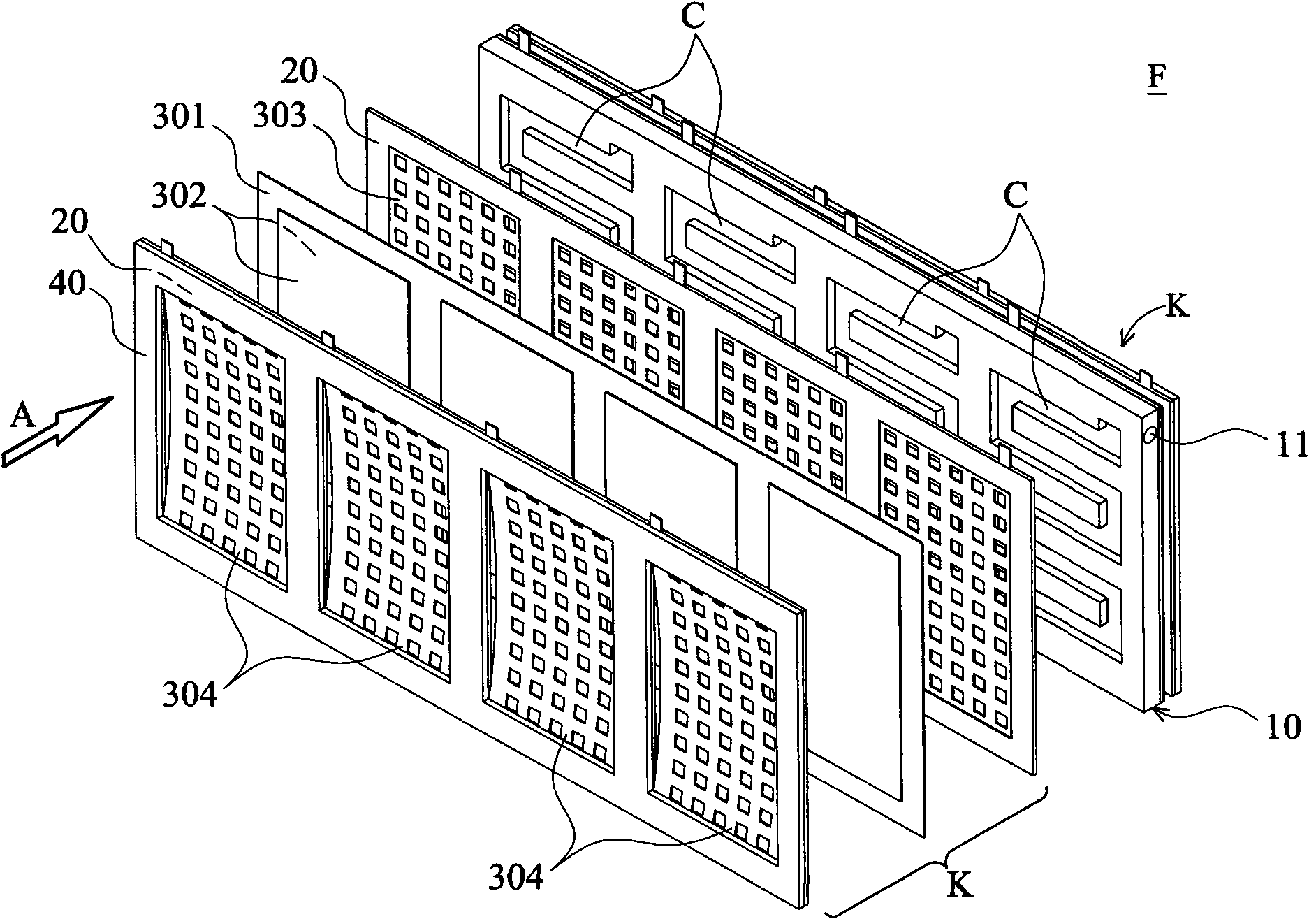
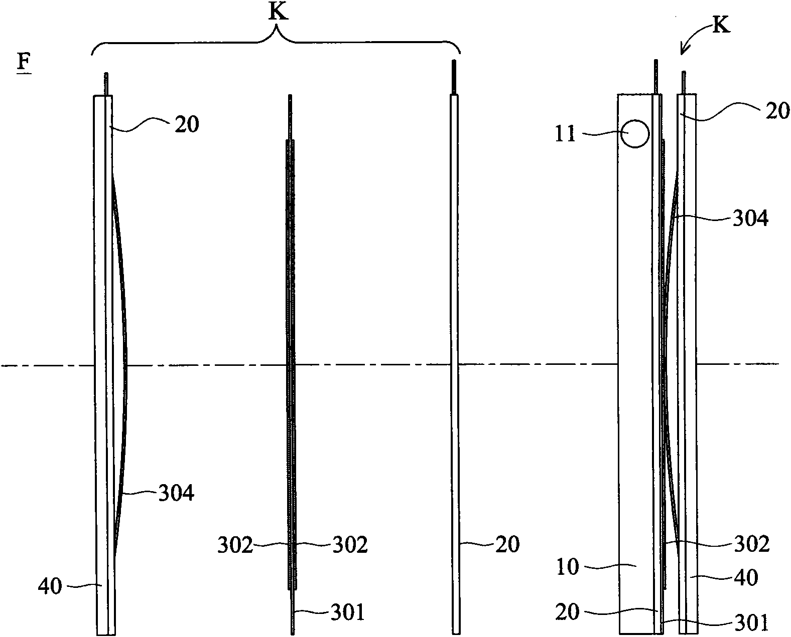
[0051] Figure 2A It is an exploded view of a fuel cell module according to an embodiment of the present invention. Figure 2B is a side view of a fuel cell module according to an embodiment of the present invention, consisting of Figure 2B The local structure of the fuel cell module before and after assembly can b...


PUM


Abstract

A fuel cell module may include a membrane electrode assembly, two gas diffusion layers, two current collectors, two sealing members, and a fluid flow plate assembly. The two gas diffusion layers are coupled with opposite sides of the membrane electrode assembly. The current collectors are coupled with the gas diffusion layers and the sealing members. The fluid flow plate assembly is coupled with the membrane electrode assembly at a first side thereof and has a channel. At least one of the membrane electrode assembly, the gas diffusion layers, the current collectors, and the sealing members has a non-planar surface at least partially flattened when the assembly occurs.

Description

technical field [0001] The invention relates to a fuel cell device, in particular to a fuel cell module capable of strengthening the contact force between internal components. Background technique [0002] The conventional flow field plate refers to a structure that can be used to carry, transmit, divide and / or distribute one or more fluids. The fluid referred to here is a general term in a broad sense, which can be any A substance that flows from one location to another. For example, the aforementioned fluid may include air, gas, liquid, or viscous fluid, etc., and the substance may flow or move from any position in the space to another position. [0003] Conventional flow field plates can be used, for example, in fuel cells to transport, guide and / or distribute one or more fuels, liquid or gaseous substances that can be used to generate electricity. figure 1 A conventional fuel cell device is disclosed, such as a single cell structure 400 of a proton exchange membrane fu...

Claims


Application Information

Patent Timeline
Patent Type & Authority Applications(China)
IPC IPC(8): H01M8/24H01M8/10H01M4/86H01M8/0258H01M8/04276
CPCY02E60/50Y02E60/521
Inventor 陈祈彰许桓瑞张文振曹芳海
Owner IND TECH RES INST
Why Eureka
Try Eureka