Heat management system and method for battery pack of electric automobile

A battery management system, electric vehicle technology, applied in the direction of secondary batteries, circuits, electrical components, etc., can solve problems such as easy leakage, complex liquid circulation structure, etc., to achieve the effect of simplified structure and simple operation

Active Publication Date: 2011-11-23
CHERY AUTOMOBILE CO LTD
View PDF1 Cites 14 Cited by
  • Summary
  • Abstract
  • Description
  • Claims
  • Application Information

AI Technical Summary

Problems solved by technology

[0004] In the process of realizing the present invention, the inventors found that the prior art

Method used


Image

  • Heat management system and method for battery pack of electric automobile
  • Heat management system and method for battery pack of electric automobile
  • Heat management system and method for battery pack of electric automobile

Examples


Example Embodiment

[0039] Example 1

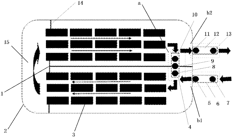
[0040] See figure 1 , The embodiment of the present invention provides a thermal management system for an electric vehicle battery pack, including a battery pack shell 2, a battery cell 3, a heating system, a heat dissipation system, and a BMS (Battery Management System, battery management system) (not shown in the figure) ). A plurality of battery cells 3 are evenly arranged in the battery pack shell 2, and the battery pack shell 2 is provided with a "T"-shaped middle wind deflector 1, such as figure 1 As shown, the length of the long plate arranged parallel to the battery cell 3 in the middle wind deflector 1 is slightly shorter than the length of the long side of the battery casing 2. One end of the long plate of the middle wind deflector 1 and the battery casing 2 The right end is connected, the short plate is set close to the left end of the battery pack shell 2, and the long plate of the middle wind deflector 1 separates the battery pack shell 2 into two ...

Example Embodiment

[0049] Example 2

[0050] See also Figure 1-Figure 3 The embodiment of the present invention utilizes the thermal management system provided in embodiment 1 to provide a thermal management method for an electric vehicle battery pack, the method includes:

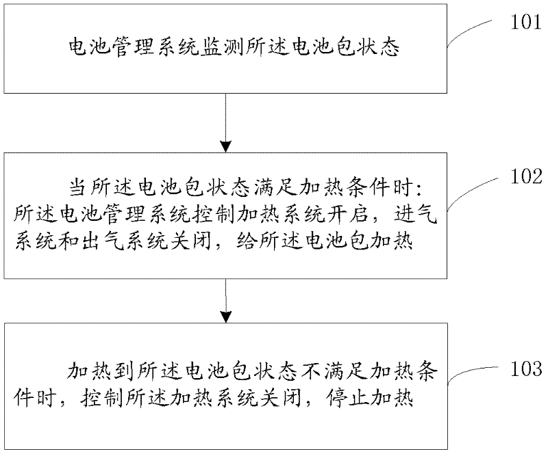
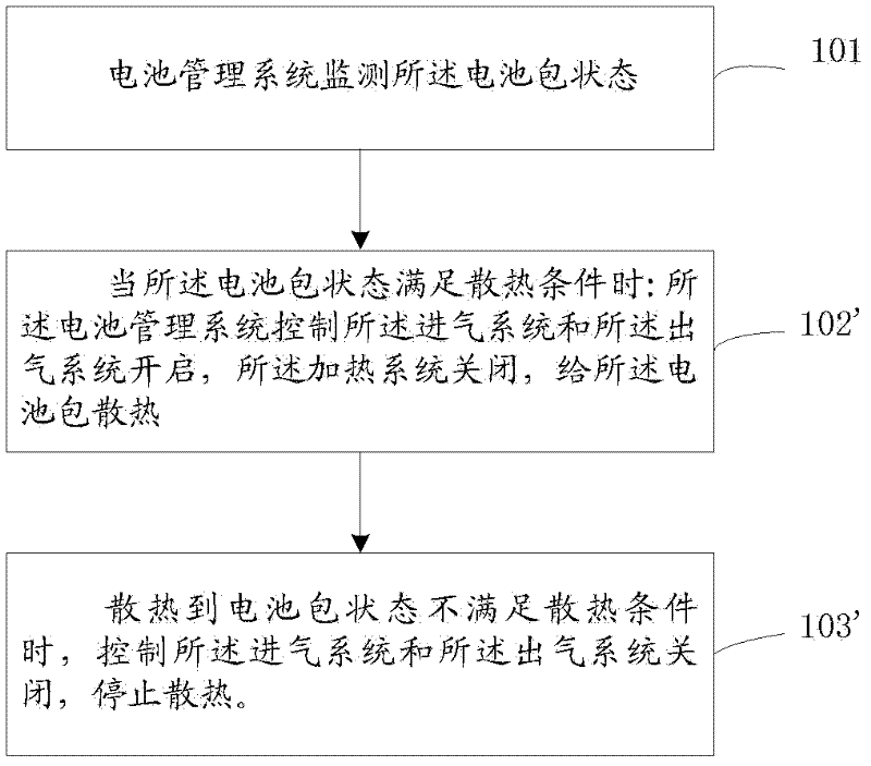
[0051] 101: BMS monitors the state of the battery pack;

[0052] 102: When the state of the battery pack meets the heating condition:

[0053] BMS controls the heating system to be turned on, and the air inlet system and the air outlet system are turned off to heat the battery pack;

[0054] At this time, the heating system heats up, and the gas inside the battery pack follows figure 1 Flow in the direction indicated by the arrow in the middle, heating each single battery.

[0055] 103: When the state of the battery pack does not meet the heating conditions, control the heating system a to turn off and stop heating;

[0056] 102': When the state of the battery pack meets the heat dissipation condition:

[0057] The BMS controls the int...


PUM


Abstract

The invention discloses a heat management system and method for a battery pack of an electric automobile, belonging to the field of heat management of a battery pack of an electric automobile. The system comprises a battery pack shell and a battery management system, wherein a T-shaped middle wind deflector is arranged inside the battery pack shell, is connected with one end of the battery pack shell and is used for partitioning the battery pack shell into two spaces; the two spaces are communicated with each other through a gap formed between the other end of the battery pack shell and the middle wind deflector; one end of the battery pack shell which is connected with the middle wind deflector is provided with a heat-radiating system and a heating system; the heat-radiating system comprises an air inlet system and an air outlet system; the air inlet system and the air outlet system are positioned on both sides of the middle wind deflector respectively, and are positioned outside the battery pack shell; and the heating system passes through the middle wind deflector and is arranged inside the battery pack shell. In the invention, the battery pack is subjected to heating and heat radiating through the air; and the heat management system has a simple structure, and is free from liquid leakage.

Description

Technical field [0001] The present invention relates to the field of thermal management of battery packs of electric vehicles, and in particular to a thermal management system for battery packs of electric vehicles and a method for thermal management of battery packs using the system. Background technique [0002] In recent years, the energy crisis and environmental degradation have become important factors restricting global development. The development and utilization of clean energy is a powerful means to solve the energy crisis and improve the environment. As an important clean energy, rechargeable batteries have been used in the field of electric vehicles as a power source. [0003] At present, rechargeable batteries used as power sources cannot work normally in extremely low temperature (less than -30°C) and extremely high temperature (greater than 50°C) environments, resulting in electric vehicles using them as energy sources cannot work normally. Therefore, thermal managem...

Claims


Application Information

Patent Timeline
IPC IPC(8): H01M10/50H01M10/625H01M10/635
CPCY02E60/12Y02E60/10
Inventor 谭巍
Owner CHERY AUTOMOBILE CO LTD
Why Eureka
Try Eureka