
Antenna assemblies for use with portable communications devices

A technology of antenna components, communication equipment, applied in the direction of antenna components, antennas, resonant antennas, etc.

Inactive Publication Date: 2011-11-23
LAIRD TECH INC
View PDF3 Cites 7 Cited by
  • Summary
  • Abstract
  • Description
  • Claims
  • Application Information

AI Technical Summary

Problems solved by technology

Unfortunately, such interference can significantly inhibit the operational utility of these devices

Method used


Image

  • Antenna assemblies for use with portable communications devices
  • Antenna assemblies for use with portable communications devices
  • Antenna assemblies for use with portable communications devices

Examples


example 1

[0049] In one example, in-band gain for FM applications was estimated for two antenna assemblies, one with an electronics protection system according to the present disclosure and one without such an electronics protection system. The gain for an antenna assembly with an electronics protection system is indicated by graph 450 and the gain for an antenna assembly without such an electronics protection system is indicated by graph 452 . Such as Figure 4 As shown, including the electronics protection system brings about negligible degradation, if any, to the performance of the antenna assembly. For example, an antenna assembly without an electronics protection system exhibits a maximum gain of approximately 2.32 decibels (dB) at a frequency of approximately 94.4 megahertz (MHz) (with a Q-factor of approximately 94.4), while an antenna assembly with an electronics protection system exhibits a maximum gain of approximately 2.32 decibels (dB) at approximately 94.4 megahertz (MHz). ...

example 2

[0051] In another example, a contact discharge (e.g., ESD contact discharge, etc.) is applied to two antenna assemblies, one antenna assembly having an electronics protection system according to the present disclosure and the other antenna assembly without such electronics Protection system antenna assembly. Antenna assemblies with electronics protection systems (e.g. amplifiers of antenna assemblies, etc.) can withstand contact discharges in excess of 8 kV (e.g., according to HBM standards, etc.), while antenna assemblies without electronics protection systems can only withstand 200 Contact discharge in volts (V) (eg, according to HBM standards, etc.).


PUM


Abstract

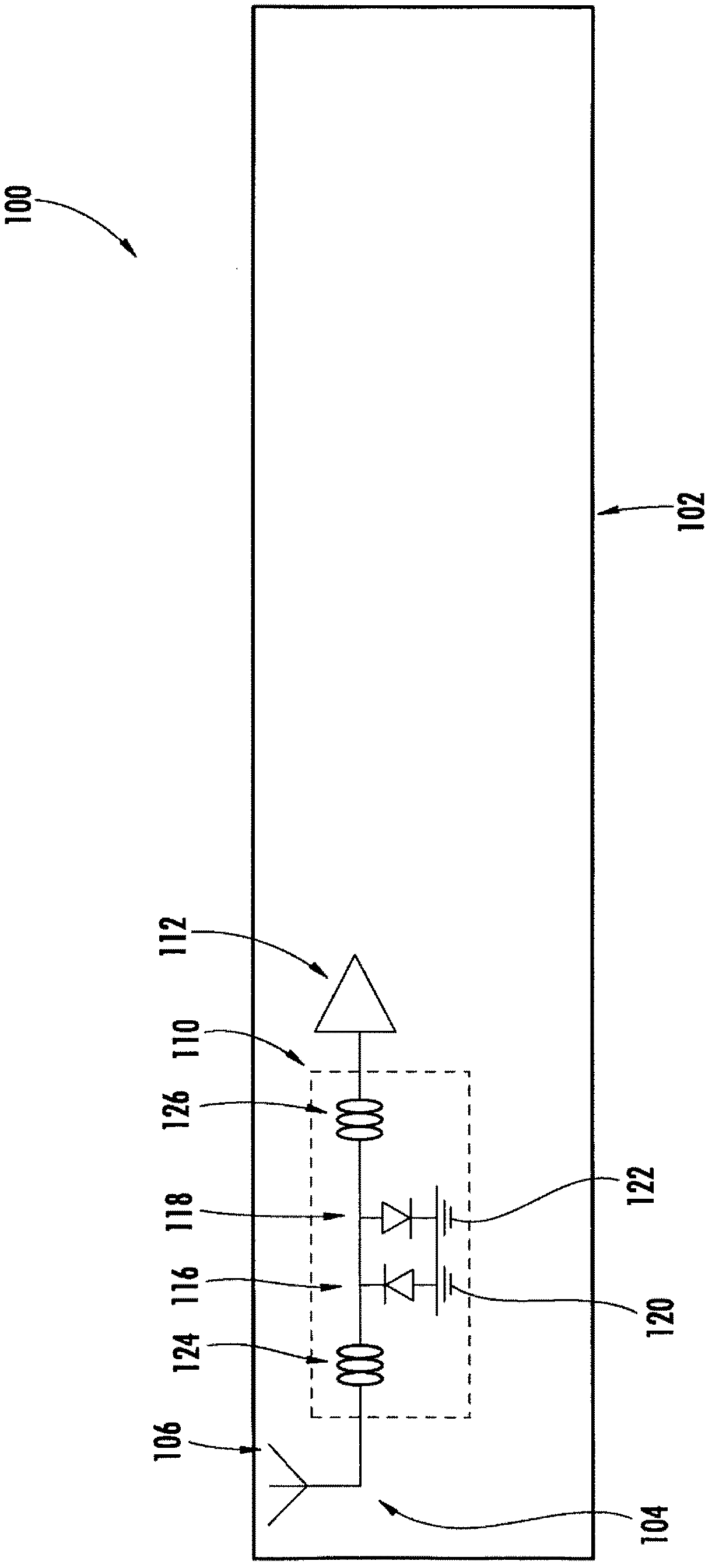
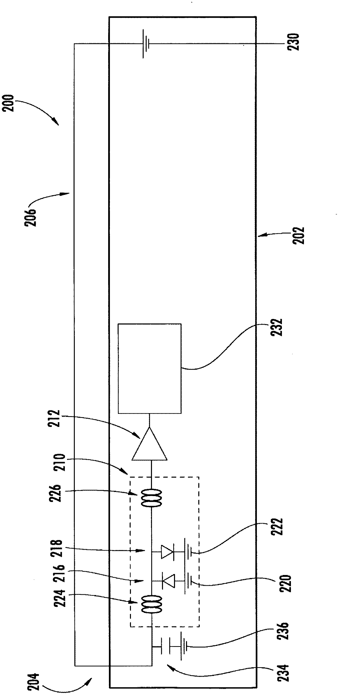
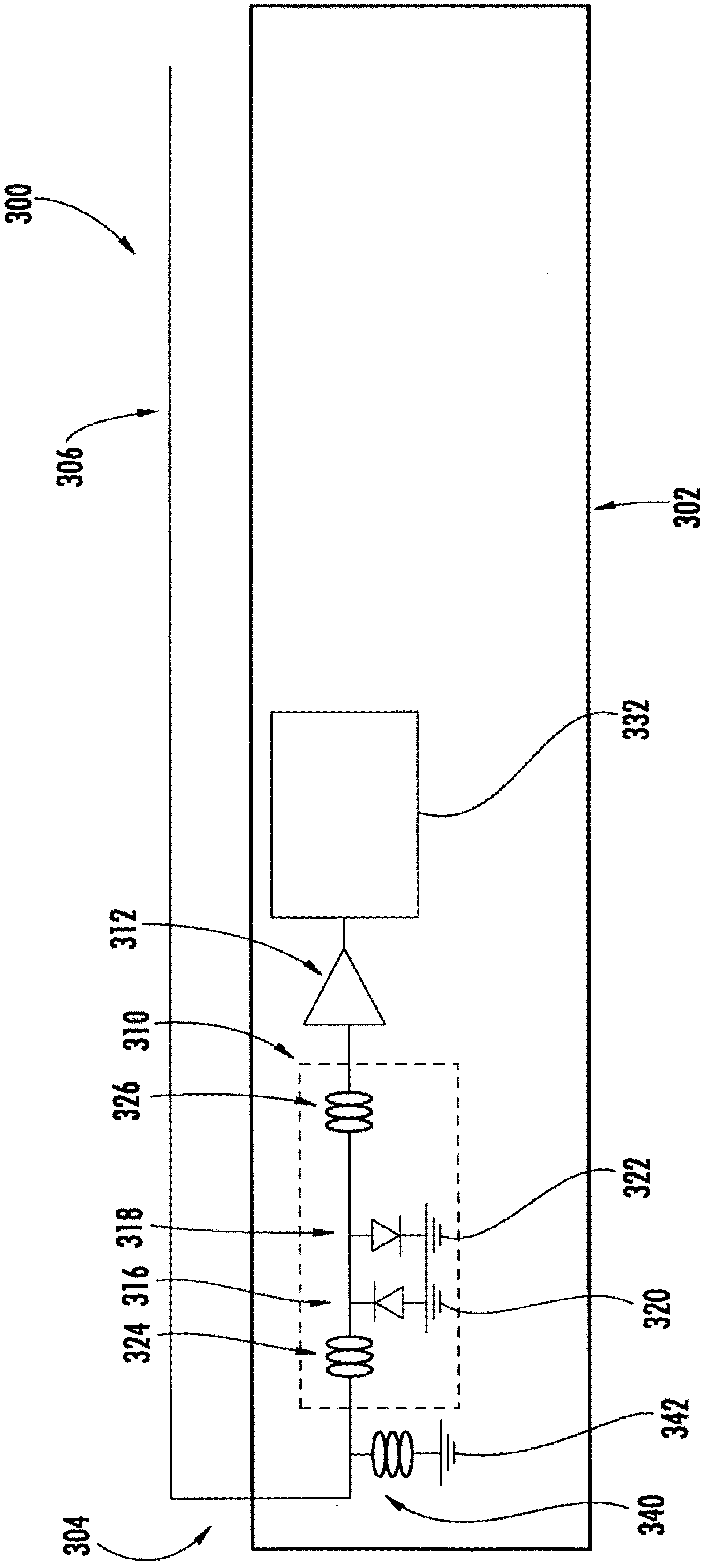
An antenna assembly generally includes an antenna element, an amplifier, and an electronics protection system coupled generally between the antenna element and the amplifier for filtering cross-talk and / or for protecting against electrostatic discharge and / or for suppressing radiated spurious emissions. The electronics protection system generally includes first and second inductors disposed in series generally between the antenna element and the amplifier, and first and second diodes coupled in shunt and disposed generally between the first and second inductors.

Description

[0001] Cross References to Related Applications [0002] This application claims priority to US Provisional Patent Application No. 61 / 139615, filed December 21, 2008, and US Provisional Patent Application No. 61 / 139882, filed December 22, 2008. The entire disclosure of the above application is hereby incorporated by reference in its entirety. technical field [0003] The present disclosure relates generally to antenna assemblies suitable for use with portable communication devices, and more particularly, to antenna assemblies having systems for, for example, suppressing electrostatic discharge and / or radiated spurious emissions. Background technique [0004] This section provides background information related to the present disclosure which is not necessarily prior art. [0005] Portable communication devices operable to provide a number of different modes of operation are becoming increasingly popular. For example, a mobile phone may typically support a voice communicati...

Claims


Application Information

Patent Timeline
IPC IPC(8): H01L27/02H01Q1/50H02H9/04H01Q7/00H01Q9/30
CPCH01Q1/50H01L27/0248H01Q9/30H01Q1/242H01Q7/00
Inventor 安德烈·凯科宁彼得·林德伯格
Owner LAIRD TECH INC
Learn More